Inst ToolsInst ToolsInst Tools
  • Courses
  • Automation
    • PLC
    • Control System
    • Safety System
    • Communication
    • Fire & Gas System
  • Instrumentation
    • Design
    • Pressure
    • Temperature
    • Flow
    • Level
    • Vibration
    • Analyzer
    • Control Valve
    • Switch
    • Calibration
    • Erection & Commissioning
  • Interview
    • Instrumentation
    • Electrical
    • Electronics
    • Practical
  • Q&A
    • Instrumentation
    • Control System
    • Electrical
    • Electronics
    • Analog Electronics
    • Digital Electronics
    • Power Electronics
    • Microprocessor
  • Request
Search
  • Books
  • Software
  • Projects
  • Process
  • Tools
  • Basics
  • Formula
  • Power Plant
  • Root Cause Analysis
  • Electrical Basics
  • Animation
  • Standards
  • 4-20 mA Course
  • Siemens PLC Course
Reading: Strain Gauge Working Principle
Share
Notification Show More
Font ResizerAa
Inst ToolsInst Tools
Font ResizerAa
  • Courses
  • Design
  • PLC
  • Interview
  • Control System
Search
  • Courses
  • Automation
    • PLC
    • Control System
    • Safety System
    • Communication
    • Fire & Gas System
  • Instrumentation
    • Design
    • Pressure
    • Temperature
    • Flow
    • Level
    • Vibration
    • Analyzer
    • Control Valve
    • Switch
    • Calibration
    • Erection & Commissioning
  • Interview
    • Instrumentation
    • Electrical
    • Electronics
    • Practical
  • Q&A
    • Instrumentation
    • Control System
    • Electrical
    • Electronics
    • Analog Electronics
    • Digital Electronics
    • Power Electronics
    • Microprocessor
  • Request
Follow US
All rights reserved. Reproduction in whole or in part without written permission is prohibited.
Inst Tools > Blog > Pressure Measurement > Strain Gauge Working Principle

Strain Gauge Working Principle

Last updated: November 23, 2017 1:15 am
Editorial Staff
Pressure Measurement
No Comments
Share
5 Min Read
SHARE

Strain Gauge Sensors or Piezoresistive sensors

Piezoresistive means “pressure-sensitive resistance,” or a resistance that changes value with applied pressure. The strain gauge is a classic example of a piezoresistive element, a typical strain gauge element shown here on the tip of my finger:

Piezoresistive (strain gauge) sensors

In order to be practical, a strain gauge must be glued (bonded) on to a larger specimen capable of withstanding an applied force (stress):

strain gauge wheatstone bridge

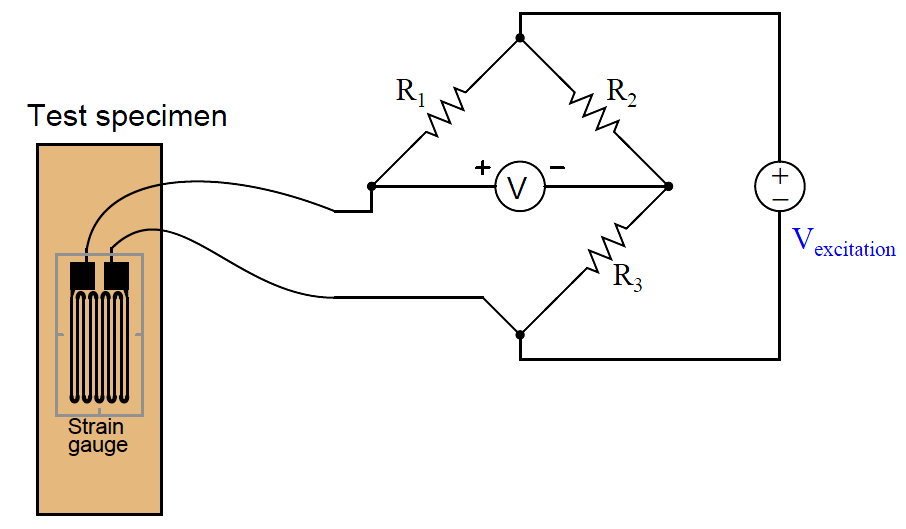
As the test specimen is stretched or compressed by the application of force, the conductors of the strain gauge are similarly deformed. Electrical resistance of any conductor is proportional to the ratio of length over cross-sectional area (R ∝ { l / A } ), which means that tensile deformation (stretching) will increase electrical resistance by simultaneously increasing length and decreasing cross-sectional area while compressive deformation (squishing) will decrease electrical resistance by simultaneously decreasing length and increasing cross-sectional area.

Attaching a strain gauge to a diaphragm results in a device that changes resistance with applied pressure. Pressure forces the diaphragm to deform, which in turn causes the strain gauge to change resistance. By measuring this change in resistance, we can infer the amount of pressure applied to the diaphragm.

The classic strain gauge system represented in the previous illustration is made of metal (both the test specimen and the strain gauge itself). Within its elastic limits, many metals exhibit good spring characteristics. Metals, however, are subject to fatigue over repeated cycles of strain (tension and compression), and they will begin to “flow” if strained beyond their elastic limit. This is a common source of error in metallic piezoresistive pressure instruments: if overpressured, they tend to lose accuracy due to damage of the spring and strain gauge elements.

Modern manufacturing techniques have made possible the construction of strain gauges made of silicon instead of metal. Silicon exhibits very linear spring characteristics over its narrow range of motion, and a high resistance to fatigue. When a silicon strain gauge is over-stressed, it fails completely rather than “flows” as is the case with metal strain gauges. This is generally considered a better result, as it clearly indicates the need for sensor replacement (whereas a metallic strain sensor may give the false impression of continued function following an over-stress event).

strain gauge with Diaphragm

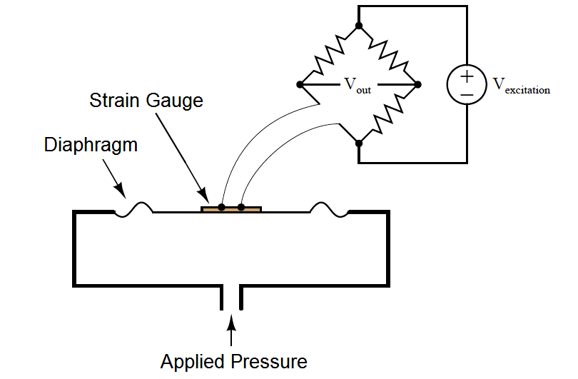
As the diaphragm bows outward with applied fluid pressure, the strain gauge stretches to a greater length, causing its resistance to increase. This change in resistance imbalances the bridge circuit, causing a voltage (Vout) proportional to the amount of applied pressure. Thus, the strain gauge works to convert an applied pressure into a measurable voltage signal which may be amplified and converted into a 4-20 mA loop current signal (or into a digital “fieldbus” signal).

In some designs, a single silicon wafer serves as both the diaphragm and the strain gauge so as to fully exploit the excellent mechanical properties of silicon (high linearity and low fatigue). However, silicon is not chemically compatible with many process fluids, and so pressure must be transferred to the silicon diaphragm/sensor via a non-reactive fill fluid (commonly a silicone-based or fluorocarbon-based liquid). A metal isolating diaphragm transfers process fluid pressure to the fill fluid, which in turn transfers pressure to the silicon wafer. Another simplified illustration shows how this works:

strain gauge element

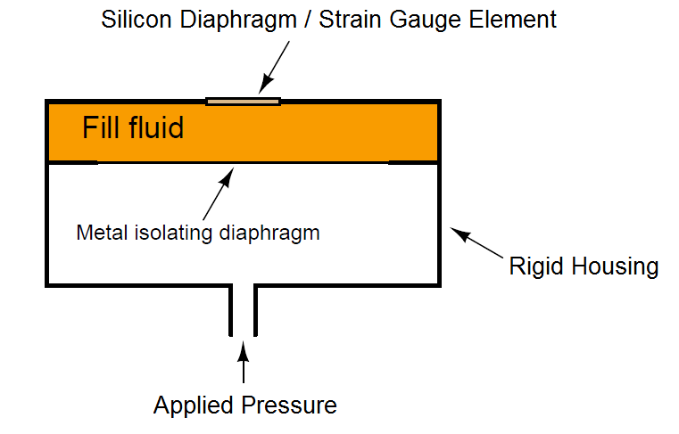
The isolating diaphragm is designed to be much more flexible (less rigid) than the silicon diaphragm, because its purpose is to seamlessly transfer fluid pressure from the process fluid to the fill fluid, not to act as a spring element. In this way, the silicon sensor experiences the same pressure that it would if it were directly exposed to the process fluid, without having to contact the process fluid. The flexibility of the metal isolating diaphragm also means it experiences much less stress than the silicon sensing diaphragm, which avoiding the problems of metal fatigue experienced by transmitter designs using metal as the sensing (spring) element.

This use of a fill fluid to transfer pressure from an isolating diaphragm to a sensing diaphragm inside the transmitter is used in most if not all modern pressure transmitter designs, even those that are not piezoresistive.

 Credits : Tony R. Kuphaldt – Creative Commons Attribution 4.0 License

Don't Miss Our Updates
Be the first to get exclusive content straight to your email.
We promise not to spam you. You can unsubscribe at any time.
Invalid email address
You've successfully subscribed !

Continue Reading

How Measurement Span of Pressure Gauge Could be Changed?
Interview Questions on Differential Pressure Flow Transmitter
Pressure Detection Circuit
Purpose of Stop in a Pressure Measuring Instrument
Pressure Gauge Installation at Pump Discharge
What is a Submersible Pressure Transmitter? Principle, Advantages
Share This Article
Facebook Whatsapp Whatsapp LinkedIn Copy Link
Share
Leave a Comment

Leave a Reply Cancel reply

Your email address will not be published. Required fields are marked *

Stay Connected

128.3kFollowersLike
69.1kFollowersFollow
210kSubscribersSubscribe
38kFollowersFollow

Categories

Explore More

PLC Raw Count Calculation for Pressure Transmitter
Uncertainty Calculations of Pressure Calibration
Components of Bourdon Tube – Questions and Answers
Commissioning a Differential Pressure Transmitter in a Pressurized Boiler Steam Drum
How to Measure Pressure in Inches of Water Column
What is a Barometer?
U-tube Manometer with equal & unequal limb types
Pressure Gauge Accessories Questions and Answers

Keep Learning

How to Connect HART Communicator with DP Transmitter

15 HART Communicator Questions

diaphragm-pressure-gauge

Diaphragm Pressure Sensors

Hammer Effect in Gauges

What is Hammer Effect in Gauges ?

Pressure Measurement using Manometer

Pressure Measurement using Manometer

Pressure Transmitter Impulse Lines Heat Trace

Pressure Transmitters Heat-traced impulse lines

Pressure Switch Construction

Basics of Pressure switches

spiral bourdon tube

Bellows, Diaphragms and Bourdon Tubes

Pressure Manometer

Types of Manometers

Learn More

Coriolis flow meter sensor coils

Coriolis Flow Meter Construction

International Standards - Types and their Details

International Standards – Types and Their Details

Compressor IP Case Discharge Temperature Gradually Increases

Compressor Anti-Surge Control near-miss incident

Configuration of Siemens Scada and PLC

Configuration of Input and Output Tags in Siemens Scada and PLC

Difference Between Modbus and Profibus

Difference Between Modbus and Profibus

principle of time base generator

Time Base Generator

Ideal Diode Characteristics Curve

Difference between ideal diode & conventional diode

Intelligent Motor Control Center

What is an Intelligent Motor Control Center? – IMCC

Menu

  • About
  • Privacy Policy
  • Copyright

Quick Links

  • Learn PLC
  • Helping Hand
  • Part Time Job

YouTube Subscribe

Follow US
All rights reserved. Reproduction in whole or in part without written permission is prohibited.
Welcome Back!

Sign in to your account

Username or Email Address
Password

Lost your password?