This is Programmable Logic Control (PLC) Application for PLC Stamping Operation.
PLC Stamping Operation
Problem Description
When part is placed on conveyor at position 1, and when cycle start button is pressed it moves to position 2. After reaching at position 2 it will stop for stamping process.
After stamping process part will go at position 3 and from here it will be taken away from conveyor manually.
Write PLC program for this process using ladder diagram language.
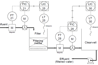
Problem Diagram

Problem Solution
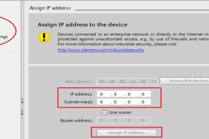
In this system, we will use S7-300 PLC and TIA portal software for programming.
Here consider one conveyor system that will move the part from one position to another position.
Three limit switches are used to sense the position of the part on the conveyor. For position 1, 2, and 3 as shown as LS1, LS2, and LS3 respectively.
A reversible motor is used for UP_motor coil for reverse direction and DN_coil for forward direction.
LSDN and LSUP limits switches are used to detect the stamper arm down and up position.
Inputs & Outputs List
Inputs List
- START PB :- I0.0
- STOP PB :- I0.1
- Limit switch for position 1 :- I0.2
- Limit switch for position 2 :- I0.3
- Limit switch for position 3 :- I0.4
- Limit switch to detect upper position :- I0.5
- Limit switch to detect down position :- I0.6
Outputs List
- UP_motor :- Q0.1
- DN_motor :- Q0.2
- Conveyor motor :- Q0.0
M memory
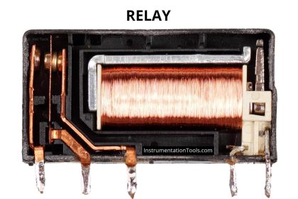
- Relay coil :- M0.0
- Relay coil 1 :- M0.1
- Relay coil 2 :- M0.2
- Relay coil 3 :- M0.3
- Relay coil 4 :- M0.4
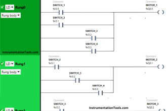
PLC Program to Operate Stamping of Parts

Program Description
For this application, we used S7-300 PLC and TIA portal software for programming.
Network 1:
If LS1 (I0.2) is detected and START PB is pressed (I0.0), internal relay coil will be ON. Here cycle will start from home position and we consider here LS1 detection is home position.
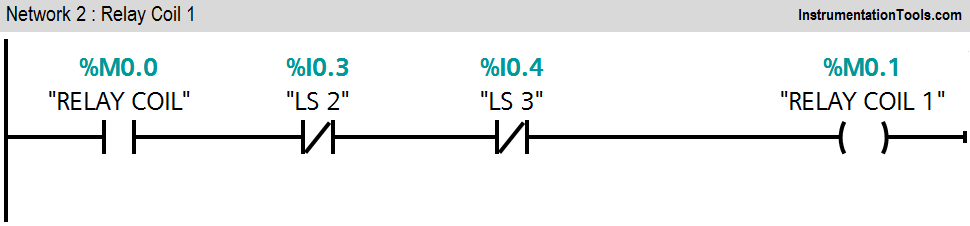
Network 2:
If both LS2 (I0.3) and LS3 (I0.4) are not detected, relay coil 1 (M0.0) will be ON.
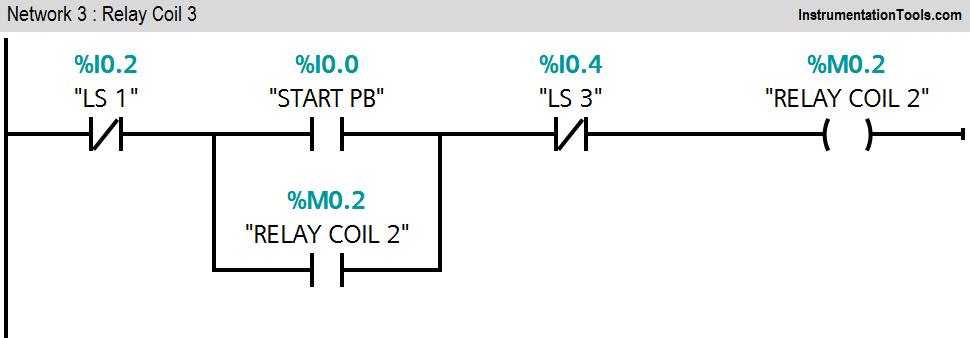
Network 3:
If LS 1 (I0.2) is not detected and START button (I0.0) is pressed, relay coil 2(M0.1) will be ON.
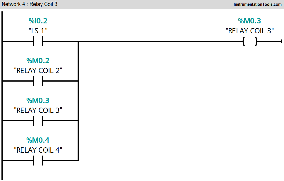
Network 4:
If anyone is detected from LS1 (I0.2), relay coil 2(M0.2) or relay coil 4(M0.4), relay coil 3(M0.3) will be latched.
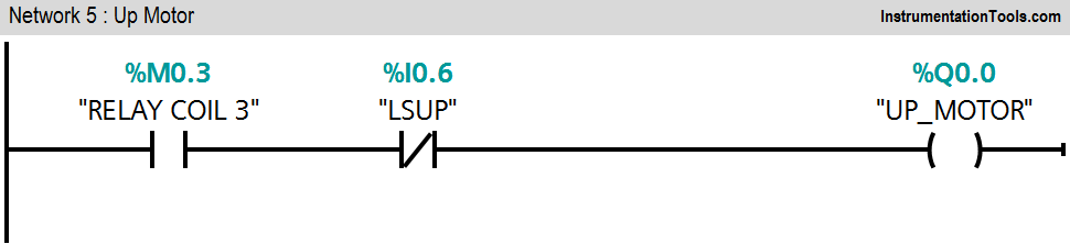
Network 5:
If relay coil 3(M0.4) is ON and LSUP (I0.5) is not detected, the motor will start reverse (stamping arm moves upper direction).
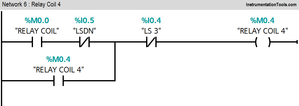
Network 6:
Relay coil 4(M0.4) will start when LSDN (I0.6) and LS 3(I0.4) are not detected.
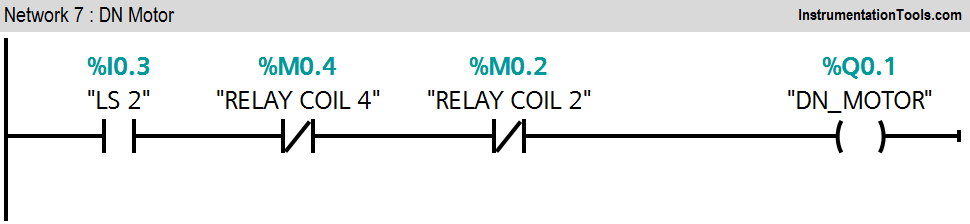
Network 7:
When LS 2(I0.3) is detected, the stamping process should start so the stamping arm will start to move forward (Q0.2).
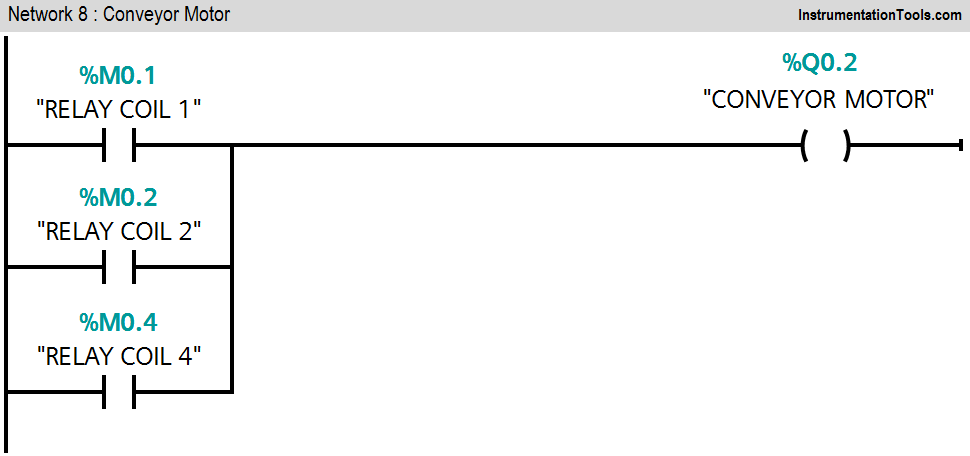
Network 8:
The conveyor motor (Q0.0) will remain in ON condition if relays 1, 2, or 3 are detected.
Here consider UP motor output meaning is stamping arm moves reverse and DN motor output meaning is stamping arm moves forward.
Relay coil, 1, 2, 3, and 4 taken for logical conditions.
Note:- Above application may be different from actual application. This example is only for explanation purpose only. We can implement this logic in other PLC also. This is the simple concept of stamping of parts in industry, we can use this concept in other examples also.
All parameters considered in example are for explanation purpose only, parameters may be different in actual applications. Also all interlocks are not considered in the application.
Author: Bhavesh
If you liked this article, then please subscribe to our YouTube Channel for PLC and SCADA video tutorials.
You can also follow us on Facebook and Twitter to receive daily updates.
Read Next:
- SR Flip Flop using PLC
- PLC D Flip Flop using PLC
- PLC Interview Questions
- Siemens S7 1200 PLC configuration