Inst ToolsInst ToolsInst Tools
  • Courses
  • Videos
  • Q & A
    • Interview
      • Instrumentation
      • Electronics
      • Electrical
      • Practical Questions
    • MCQ
      • Instrumentation MCQ
      • Electrical MCQ
      • Electronics MCQ
      • Control Systems MCQ
      • Analog Electronics MCQ
      • Digital Electronics MCQ
      • Power Electronics MCQ
      • Microprocessor MCQ
      • Multiple Choice Questions
  • EE
    • Electronics
      • Electronics Q & A
      • Electronic Basics
      • Electronic Devices & Circuits
      • Electronics Animation
      • Digital Electronics
    • Electrical
      • Electrical Basics
      • Electrical Q & A
      • Power Electronics
      • Electrical Machines
      • Electrical Animation
      • Power Systems
      • Switchgear & Protection
      • Transmission & Distribution
  • Measure
    • Control Valves
    • Calibration
    • Temperature
    • Pressure
    • Flow
    • Level
    • Analyzers
    • Switches
    • Vibration
    • Solenoid Valve
  • Control
    • PLC Tutorials
    • Control Systems
    • Safety Instrumented System (SIS)
    • Communication
    • Fire & Gas System
  • More
    • Design
    • Tools
    • Animation
    • Basics
    • Formulas
    • Standards
    • TextBooks
    • Common
    • Software
    • Excel Tools
    • Erection & Commissioning
    • Process Fundamentals
    • Videos
    • Books
Search
All rights reserved. Reproduction in whole or in part without written permission is prohibited.
Reading: Power Factor Meter Principle
Share
Notification Show More
Font ResizerAa
Inst ToolsInst Tools
Font ResizerAa
  • Courses
  • PLC Tutorials
  • Control Systems
Search
  • Courses
  • Videos
  • Q & A
    • Interview
    • MCQ
  • EE
    • Electronics
    • Electrical
  • Measure
    • Control Valves
    • Calibration
    • Temperature
    • Pressure
    • Flow
    • Level
    • Analyzers
    • Switches
    • Vibration
    • Solenoid Valve
  • Control
    • PLC Tutorials
    • Control Systems
    • Safety Instrumented System (SIS)
    • Communication
    • Fire & Gas System
  • More
    • Design
    • Tools
    • Animation
    • Basics
    • Formulas
    • Standards
    • TextBooks
    • Common
    • Software
    • Excel Tools
    • Erection & Commissioning
    • Process Fundamentals
    • Videos
    • Books
Follow US
All rights reserved. Reproduction in whole or in part without written permission is prohibited.
Inst Tools > Blog > Electrical Theory > Power Factor Meter Principle

Power Factor Meter Principle

Last updated: August 13, 2018 11:56 am
Editorial Staff
Electrical Theory
No Comments
Share
1 Min Read
SHARE

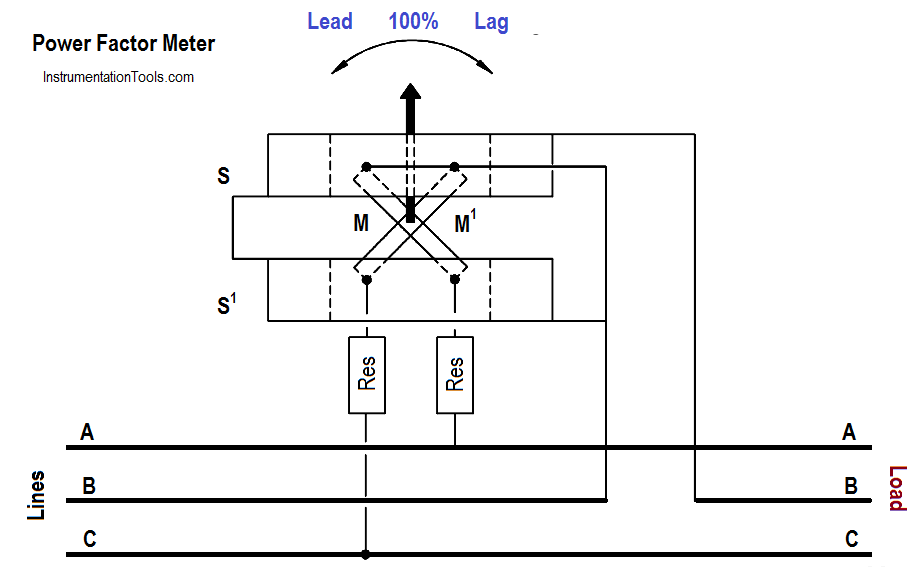
A power factor meter is a type of electrodynamometer movement when it is made with two movable coils set at right angles to each other. The method of connection of this type of power factor meter, in a 3φ circuit, is shown in Figure.

Power Factor Meter Principle

The two stationary coils, S and S1 , are connected in series in Phase B. Coils M and M1 are mounted on a common shaft, which is free to move without restraint or control springs. These coils are connected with their series resistors (Res) from Phase B to Phase A and from Phase B to Phase C.

At a power factor of unity, one potential coil current leads and one lags the current in Phase B by 30°; thus, the coils are balanced in the position shown in Figure.

A change in power factor will cause the current of one potential coil to become more in phase and the other potential coil to be more out of phase with the current in Phase B, so that the moving element and pointer take a new position of balance to show the new power factor.
Don't Miss Our Updates
Be the first to get exclusive content straight to your email.
We promise not to spam you. You can unsubscribe at any time.
Invalid email address
You've successfully subscribed !

Continue Reading

Units of Electrical Measurement
Full-Wave Rectifier Circuit
DC Generator Theory
Impedance
Applying Kirchhoff’s Current Law
DC Motor Theory
Share This Article
Facebook Whatsapp Whatsapp LinkedIn Copy Link
Share
Leave a Comment

Leave a Reply Cancel reply

Your email address will not be published. Required fields are marked *

Stay Connected

128.3kFollowersLike
69.1kFollowersFollow
208kSubscribersSubscribe
38kFollowersFollow

Categories

Explore More

Single Phase Power Wiring Schemes
Impedance in RLC Circuits
Parallel Circuit Current Calculations
Multimeter & Megger Principle
Unbalanced 3 Phase Loads
Induction Motor Torque Versus Slip
Transformer Impedance Ratio
Current Division
Transformer Operation Under No-Load
Starting a Synchronous Motor

Keep Learning

Series-Wound DC Generator Principle

Series-Wound DC Generators

Voltage Polarities

Voltage Polarity and Current Direction

Potential Difference Across a Conductor Causes a Current to Flow

Conductor, Insulator, Resistor and Current Flow

Voltage and Current Phase Relationships in an Inductive Circuit

Voltage and Current Phase Relationships in an Inductive Circuit

Cutaway View of Circuit Breaker

Low Voltage Air Circuit Breaker Principle

D’Arsonval Movement

D’Arsonval Meter Movement

Block Diagram

Block Diagram

Types of Fuses

Electrical System Components and Protection Devices

Discover More

How to Select Right Thermocouple and Thermowell

How to Select Right Thermocouple & Thermowell ?

PLC Programming Basics for a Packing Machine Control System

PLC Packing Machine Control System Program in XG5000

failure rate of a component - 1

Failure rate and MTBF of Safety Instrumented Systems

Intelligent Motor Control Center

What is an Intelligent Motor Control Center? – IMCC

ATEX Standards

ATEX Standards

Integral Wind-Up Limitation

What is Integral Wind Up ?

What is electrical transformer

Transformer Impedance Ratio

Basic Principles of Electricity

Basic Principles of Electricity

Follow US
All rights reserved. Reproduction in whole or in part without written permission is prohibited.
Welcome Back!

Sign in to your account

Username or Email Address
Password

Lost your password?