Inst ToolsInst ToolsInst Tools
  • Ask
  • Courses
  • Videos
  • Q & A
    • Interview
      • Instrumentation
      • Electronics
      • Electrical
      • Practical Questions
    • MCQ
      • Instrumentation MCQ
      • Electrical MCQ
      • Electronics MCQ
      • Control Systems MCQ
      • Analog Electronics MCQ
      • Digital Electronics MCQ
      • Power Electronics MCQ
      • Microprocessor MCQ
      • Multiple Choice Questions
  • EE
    • Electronics
      • Electronics Q & A
      • Electronic Basics
      • Electronic Devices & Circuits
      • Electronics Animation
      • Digital Electronics
    • Electrical
      • Electrical Basics
      • Electrical Q & A
      • Power Electronics
      • Electrical Machines
      • Electrical Animation
      • Power Systems
      • Switchgear & Protection
      • Transmission & Distribution
  • Measure
    • Control Valves
    • Calibration
    • Temperature
    • Pressure
    • Flow
    • Level
    • Analyzers
    • Switches
    • Vibration
    • Solenoid Valve
  • Control
    • PLC Tutorials
    • Control Systems
    • Safety Instrumented System (SIS)
    • Communication
    • Fire & Gas System
  • More
    • Design
    • Tools
    • Animation
    • Basics
    • Formulas
    • Standards
    • TextBooks
    • Common
    • Software
    • Excel Tools
    • Erection & Commissioning
    • Process Fundamentals
    • Videos
    • Books
Search
All rights reserved. Reproduction in whole or in part without written permission is prohibited.
Reading: AC Generation
Share
Notification Show More
Font ResizerAa
Inst ToolsInst Tools
Font ResizerAa
  • Courses
  • PLC Tutorials
  • Control Systems
Search
  • Ask
  • Courses
  • Videos
  • Q & A
    • Interview
    • MCQ
  • EE
    • Electronics
    • Electrical
  • Measure
    • Control Valves
    • Calibration
    • Temperature
    • Pressure
    • Flow
    • Level
    • Analyzers
    • Switches
    • Vibration
    • Solenoid Valve
  • Control
    • PLC Tutorials
    • Control Systems
    • Safety Instrumented System (SIS)
    • Communication
    • Fire & Gas System
  • More
    • Design
    • Tools
    • Animation
    • Basics
    • Formulas
    • Standards
    • TextBooks
    • Common
    • Software
    • Excel Tools
    • Erection & Commissioning
    • Process Fundamentals
    • Videos
    • Books
Follow US
All rights reserved. Reproduction in whole or in part without written permission is prohibited.
Inst Tools > Blog > Electrical Theory > AC Generation

AC Generation

Last updated: July 29, 2018 6:26 pm
Editorial Staff
Electrical Theory
1 Comment
Share
3 Min Read
SHARE

An understanding of how an AC generator develops an AC output will help the student analyze the AC power generation process.

The elementary AC generator (Figure 1) consists of a conductor, or loop of wire in a magnetic field that is produced by an electromagnet. The two ends of the loop are connected to slip rings, and they are in contact with two brushes. When the loop rotates it cuts magnetic lines of force, first in one direction and then the other.

AC Generator

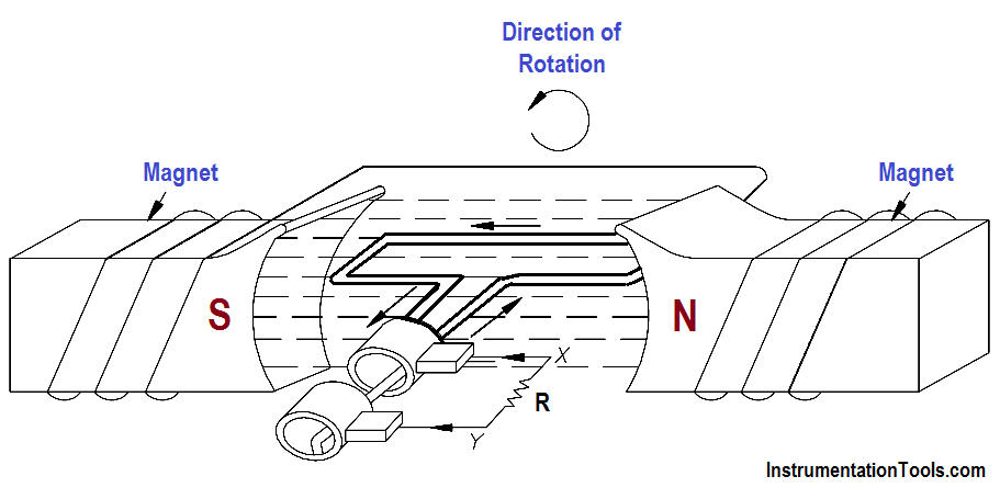
Figure 1 : Simple AC Generator

Development of a Sine-Wave Output

At the instant the loop is in the vertical position (Figure 2, 0o ), the coil sides are moving parallel to the field and do not cut magnetic lines of force. In this instant, there is no voltage induced in the loop. As the coil rotates in a counter-clockwise direction, the coil sides will cut the magnetic lines of force in opposite directions. The direction of the induced voltages depends on the direction of movement of the coil.

The induced voltages add in series, making slip ring X (Figure 1) positive (+) and slip ring Y (Figure 1) negative (-). The potential across resistor R will cause a current to flow from Y to X through the resistor. This current will increase until it reaches a maximum value when the coil is horizontal to the magnetic lines of force (Figure 2, 90o ).

The horizontal coil is moving perpendicular to the field and is cutting the greatest number of magnetic lines of force. As the coil continues to turn, the voltage and current induced decrease until they reach zero, where the coil is again in the vertical position (Figure 2, 180o ). In the other half revolution, an equal voltage is produced except that the polarity is reversed (Figure 2, 270o, 360o ). The current flow through R is now from X to Y (Figure 1).

Developing a Sine-Wave Voltage of Motor

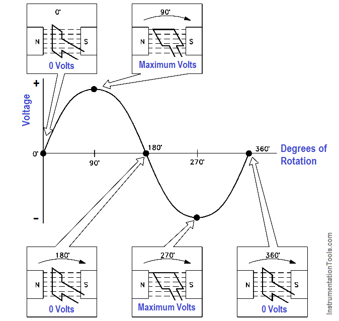
Figure 2 : Developing a Sine-Wave Voltage

The periodic reversal of polarity results in the generation of a voltage, as shown in Figure 2. The rotation of the coil through 360° results in an AC sine wave output.

Don't Miss Our Updates
Be the first to get exclusive content straight to your email.
We promise not to spam you. You can unsubscribe at any time.
Invalid email address
You've successfully subscribed !
Transformer Voltage Ratio
Low Voltage Air Circuit Breaker Principle
Transformer Mutual Induction
Resonance, Resonant Frequency, Series and Parallel Resonance
Series-Wound Motor
Share This Article
Facebook Whatsapp Whatsapp LinkedIn Copy Link
Share
1 Comment
  • DONAN TAYLOR says:
    May 24, 2019 at 6:22 pm

    Thanks for the simplicity in explaining important concepts

    Reply

Leave a Reply Cancel reply

Your email address will not be published. Required fields are marked *

Stay Connected

128.3kFollowersLike
69.1kFollowersFollow
208kSubscribersSubscribe
38kFollowersFollow

Categories

Recent Comments

  • Kamli on Top Free PLC Software
  • Guifty Shimica on Top Non-PLC Certification Courses for Automation Professionals
  • Guifty Shimica on Top Non-PLC Certification Courses for Automation Professionals
  • MIHARITSOA Aina Sitraka on Top Non-PLC Certification Courses for Automation Professionals

Related Articles

Parallel RLC Circuit

Impedance in RLC Circuits

induction motor torque versus speed

Induction Motor Torque Versus Slip

Unbalanced 3 Phase Loads

Unbalanced 3 Phase Loads

Voltage Drop in a Series Circuit

Series Resistance

Capacitors Connected in Parallel

Series and Parallel Capacitors

Electric Short Circuit

Series Short Circuit Faults

Simple RL Circuit

Impedance in RL Circuits

Electric Open Circuit

Series Open Circuit Faults

More Articles

energy-diagrams-for-insulator-semiconductor-and-conductor

Band Gap for Semiconductor Materials

Process Control Automation PLC Quiz

Process Control Automation PLC Quiz

traffic light plc program

Traffic Light Control using PLC Ladder Logic

Types of Pressure Measuring Scales

Types of Pressure Measuring Scales

Electrical Projects Ideas

Latest Electrical Projects Ideas for Final Year Students

Smart Transmitter Calibration Tutorial

Smart Transmitter Calibration Tutorial Part 1

Instrumentation Engineering Documents

Instrumentation Engineering Documents Questions Answers

Electromechanical_Relays Circuit

Relay Loop Back Circuit

Follow US
All rights reserved. Reproduction in whole or in part without written permission is prohibited.
Welcome Back!

Sign in to your account

Username or Email Address
Password

Lost your password?