Inst ToolsInst ToolsInst Tools
  • Courses
  • Automation
    • PLC
    • Control System
    • Safety System
    • Communication
    • Fire & Gas System
  • Instrumentation
    • Design
    • Pressure
    • Temperature
    • Flow
    • Level
    • Vibration
    • Analyzer
    • Control Valve
    • Switch
    • Calibration
    • Erection & Commissioning
  • Interview
    • Instrumentation
    • Electrical
    • Electronics
    • Practical
  • Q&A
    • Instrumentation
    • Control System
    • Electrical
    • Electronics
    • Analog Electronics
    • Digital Electronics
    • Power Electronics
    • Microprocessor
  • Request
Search
  • Books
  • Software
  • Projects
  • Process
  • Tools
  • Basics
  • Formula
  • Power Plant
  • Root Cause Analysis
  • Electrical Basics
  • Animation
  • Standards
  • 4-20 mA Course
  • Siemens PLC Course
Reading: Guided Wave Radar Level Sensor Pressure and Temperature Effects
Share
Notification Show More
Font ResizerAa
Inst ToolsInst Tools
Font ResizerAa
  • Courses
  • Design
  • PLC
  • Interview
  • Control System
Search
  • Courses
  • Automation
    • PLC
    • Control System
    • Safety System
    • Communication
    • Fire & Gas System
  • Instrumentation
    • Design
    • Pressure
    • Temperature
    • Flow
    • Level
    • Vibration
    • Analyzer
    • Control Valve
    • Switch
    • Calibration
    • Erection & Commissioning
  • Interview
    • Instrumentation
    • Electrical
    • Electronics
    • Practical
  • Q&A
    • Instrumentation
    • Control System
    • Electrical
    • Electronics
    • Analog Electronics
    • Digital Electronics
    • Power Electronics
    • Microprocessor
  • Request
Follow US
All rights reserved. Reproduction in whole or in part without written permission is prohibited.
Inst Tools > Blog > Instrumentation Design > Guided Wave Radar Level Sensor Pressure and Temperature Effects

Guided Wave Radar Level Sensor Pressure and Temperature Effects

Last updated: July 7, 2020 12:58 pm
Editorial Staff
Instrumentation Design Level Measurement
No Comments
Share
2 Min Read
SHARE

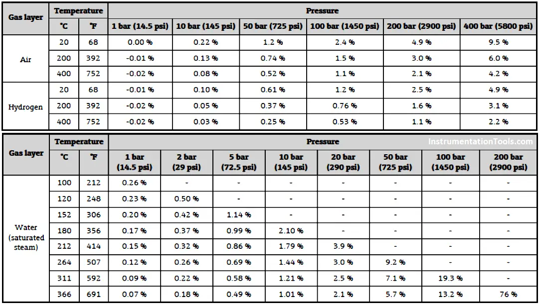
High pressures/temperatures reduce the propagation velocity of the measuring signals in the gas/vapour above the liquid interface to be measured. The result of the high pressure/temperature is a systematic measuring error.

Guided Wave Radar Level Sensor

Table gives several measuring errors for different gases/vapours.

Guided Wave Radar Level Sensor Pressure and Temperature Effects

Table – Example of measuring error on wave radar with high pressure/temperature

These errors may be compensated with two main methods:

  • compensation with external pressure and temperature sensors
  • compensation with a reference signal.

Compensation with external pressure and temperature sensor is achieved by calculation with external pressure and temperature sensors.

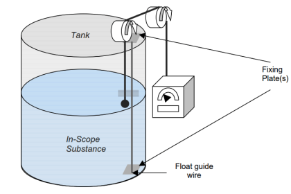
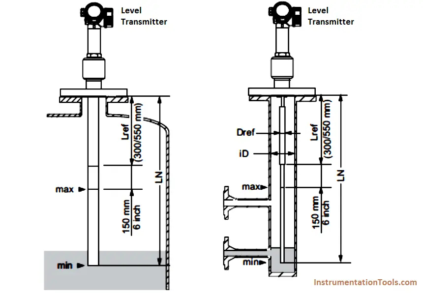
Compensation with a reference signal means that the actual wave velocity is measured by calculating a reference reflection between two known points a known distance (Lref) and relevant transit time.

Lref = Actual Velocity × Transit time of this Lref.

Having this Actual Velocity in the media, the distance can be calculated from the actual reflection time measurement. The Lref should be upper the higher maximum interface level with a margin (e.g. 150 mm in Figure).

Guided Wave Radar Level Transmitter Compensation

Figure – Example of high pressure/temperature compensation with reference signal mounting arrangement

Source: International Association of Oil & Gas Producers

Acknowledgements: IOGP Instrumentation and Automaton Standards Subcommittee (IASSC), BG Group, BP, Endress + Hauser, Emerson, Honeywell, Krohne, Petrobras, PETRONAS Carigali Sdn Bhd, Repsol, Siemens, Statoil, Total, Vega, Yokogawa.
Don't Miss Our Updates
Be the first to get exclusive content straight to your email.
We promise not to spam you. You can unsubscribe at any time.
Invalid email address
You've successfully subscribed !

Continue Reading

Contact Type Guided Wave Radar Level Transmitter Working Principle
Potentiometric Level Measurement Principle
DP Transmitter Dry Leg & Wet Leg Calculations
Level Gauge Design
Difference between Axial and Radial Diaphragm Seal Connection?
Non Contact RADAR Level Transmitter Principle, Limitations, Design, Installation and Calibration
Share This Article
Facebook Whatsapp Whatsapp LinkedIn Copy Link
Share
Leave a Comment

Leave a Reply Cancel reply

Your email address will not be published. Required fields are marked *

Stay Connected

128.3kFollowersLike
69.1kFollowersFollow
210kSubscribersSubscribe
38kFollowersFollow

Categories

Explore More

Ultrasonic Tank Gauging
Bubbler Level Sensor
Redundant Power Supply for Critical Field Panels
Solenoid Operated Valves and Latching Valves
How to Solve Cable Tray Sagging ?
Level Troll working principle
How to select a load cell?
Displacer Interface Level Measurement

Keep Learning

Switch Contact checking with oscilloscope

What is Contact bounce ?

What's the problem with shock and vibration

What’s the problem with shock and vibration ?

Voting System in PLC

Voting Concept in Package Safety System

Kv-value of a valve is determined by a standardised test

Calculate Flow Coefficient Kv of Solenoid Valve

How Buoyant Force instruments Works

How Buoyant Force instruments Works ?

Diaphragm seal for pressure measurement device

When to use a Diaphragm Seal?

Open Tank DP Level Measurement

Open Tank DP Level Transmitter Calculations

Variable Area Flow Meters

All About Variable Area Flow Meters

Learn More

Ammonia Gas Detector Calibration

Ammonia Gas Detector Working Principle and Calibration

Create an Application in HMI using Tia Portal

Create an Application in HMI using Tia Portal

non-contact pyrometer principle

Non-contact Temperature Sensors

Submersible Pressure Transmitter

What is a Submersible Pressure Transmitter? Principle, Advantages

What is an RTU - Remote Terminal Unit

What is an RTU? – Remote Terminal Unit

Feedback Pneumatic Load cell Objective Questions

Feedback Pneumatic Load cell Objective Questions

De-energized Electrical Circuits

De-energized Electrical Circuits, Networks, and Equipment

Liquid Level Switch Control Pump and Lamp

Liquid Level Switch Control Pump and Lamp

Menu

  • About
  • Privacy Policy
  • Copyright

Quick Links

  • Learn PLC
  • Helping Hand
  • Part Time Job

YouTube Subscribe

Follow US
All rights reserved. Reproduction in whole or in part without written permission is prohibited.
Welcome Back!

Sign in to your account

Username or Email Address
Password

Lost your password?