Make a PLC program to implement a totalizer for the flow meter. The flow meter has 4-20mA output that represents 0 to 100 liters/hour fuel flow in a pipe.
PLC Program for Flow Totalizer
By using this logic, we can calculate total fuel passed from the pipe.
When the totalizer value reaches 5000 liters, then automatically it should be reset or we can reset the value using the RESET button.

Problem Solution
We can solve this problem by simple logic. Here we consider a flow meter for measuring the fuel with a maximum flow rate of 100 liters/hour.
Here we will convert this flow rate from L/H to L/Sec by using DIV instruction for calculation.
After that by using 1 second clock pulse, we will store this value in another memory location and every second new value will be added & updated.
Here for example we consider the max value for the totalizer to be 5000 liters so after this value totalizer should be RESET.
So we will compare this value with the actual value and reset it automatically or we will provide a RESET button to reset the totalizer value.
List of Inputs/Outputs
Inputs List
- Reset:- I0.0
M Memory
- M0.5:- 1 second (1s) clock pulse
- M1.2:- Positive edge of clock pulse
- MD10:- Memory word for final output (L/H) of flow meter
- MD18:- Memory word for final output (L/Sec) of flow meter
- MD22:-Total liters addition
- MD26:-Total fuel in liter
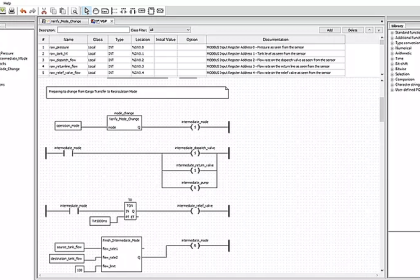
Ladder Diagram for Totalizer


Program Explained
In this problem, we will consider S7-300 PLC and TIA portal software for programming.
Network 1:
Here we have taken final output value of the flow meter in L/H (MD10). By using DIV instruction we converted L/H flow into L/sec and final value stored in MD18.
Network 2:
Here clock pulse of 1s (M0.5) will add value every second and store the result in memory word MD22.
Network 3:
Here we moved value of MD22 in MD26 (total fuel in liter) for display purpose.
Network 4:
In this network we need to reset totalizer. If total fuel is greater than 5000 (5000 value is for example purpose, it is depended on flow meter configuration & it’s range ) then totalizer count should be zero automatically or we can reset by pressing RESET button (I0.0).
Note: The above logic is for explanation purpose only. Here we have considered only final output of the scaling, so we have not mentioned 4-20mA scaling in the logic.
Result

Author: Bhavesh
If you liked this article, then please subscribe to our YouTube Channel for PLC and SCADA video tutorials.
You can also follow us on Facebook and Twitter to receive daily updates.
Read Next:
- Process Interlocks and Trips
- Motor Speed Control using VFD
- D Flip Flop PLC Ladder Logic
- PLC Oil and Water Separation
- Conditional Control Logic using PLC


hi admin, I0.0 receives the signal from the flow meter. so how to get the signal of I0.0 to MD10. I don’t understand that place
I0.0 goes through analogue scaling that is into norm x and scale x, the output of scale x is md10.
or you can give I0.0 to md10 through analogue input mapping using move function
Hi, i want to inform you that i tested this program but after period of time there is a difference between the total in flowmeter and in the program.
Can we solve this issue by taking pulse signal as input and use in the program in place of 1s pulse ?
Hi Reda, the flowmeter is more accurate. The example given is a rough PLC totaliser using a slow sample interval of 1 sec so it’s gonna have high error.
Yes taking pulses from the flowmeter will make it as accurate as the flowmeter itself, but you may need a high speed counter on your PLC to accommodate it if the frequency of pulses is fast.
Hello! Thank you for your topic. I have a question, I use Mitsubishi FX3U PLC and FX3u-4AD analog input module. PLC has 30 Ms scan cycle time and flow meter make request each second, but PLC make request every 30 Ms, how can I solve this problem?