Inst ToolsInst ToolsInst Tools
  • Courses
  • Automation
    • PLC
    • Control System
    • Safety System
    • Communication
    • Fire & Gas System
  • Instrumentation
    • Design
    • Pressure
    • Temperature
    • Flow
    • Level
    • Vibration
    • Analyzer
    • Control Valve
    • Switch
    • Calibration
    • Erection & Commissioning
  • Interview
    • Instrumentation
    • Electrical
    • Electronics
    • Practical
  • Q&A
    • Instrumentation
    • Control System
    • Electrical
    • Electronics
    • Analog Electronics
    • Digital Electronics
    • Power Electronics
    • Microprocessor
  • Request
Search
  • Books
  • Software
  • Projects
  • Process
  • Tools
  • Basics
  • Formula
  • Power Plant
  • Root Cause Analysis
  • Electrical Basics
  • Animation
  • Standards
  • 4-20 mA Course
  • Siemens PLC Course
Reading: PLC Program for Positive Edge Pulse Output for One Scan Cycle
Share
Font ResizerAa
Inst ToolsInst Tools
Font ResizerAa
  • Courses
  • Design
  • PLC
  • Interview
  • Control System
Search
  • Courses
  • Automation
    • PLC
    • Control System
    • Safety System
    • Communication
    • Fire & Gas System
  • Instrumentation
    • Design
    • Pressure
    • Temperature
    • Flow
    • Level
    • Vibration
    • Analyzer
    • Control Valve
    • Switch
    • Calibration
    • Erection & Commissioning
  • Interview
    • Instrumentation
    • Electrical
    • Electronics
    • Practical
  • Q&A
    • Instrumentation
    • Control System
    • Electrical
    • Electronics
    • Analog Electronics
    • Digital Electronics
    • Power Electronics
    • Microprocessor
  • Request
Follow US
All rights reserved. Reproduction in whole or in part without written permission is prohibited.
Inst Tools > Blog > Guest Articles > PLC Program for Positive Edge Pulse Output for One Scan Cycle

PLC Program for Positive Edge Pulse Output for One Scan Cycle

This is a PLC Program for Positive edge pulse output for one scan cycle. Learn the ladder logic with the solution.

Last updated: November 3, 2023 10:51 am
Editorial Staff
Guest Articles PLC Tutorials
No Comments
Share
6 Min Read
SHARE

This is a PLC Program for Positive edge pulse output for one scan cycle. Learn the ladder logic with the solution.

Contents
Positive Edge Pulse OutputProblemSolutionList of Inputs/OutputsPLC Ladder LogicPLC Logic DescriptionResult

Positive Edge Pulse Output

Problem Description

In some applications, we need to run an operation/function based on external input signal. We can use a digital input as trigger command to activate that required function.

Sometimes we use positive transition of the digital input signal to trigger the command instead of continuous/full pulse digital input signal.

Here we consider an example of simple logic in which two registers values will be increment after receiving the trigger command. Each register have a preset value say value “1”. So on every trigger command, the adder register values will be increment by value “1”.

For adder 1 register we use positive edge (0 to 1) triggered input and for adder 2 register we use simple digital input  (0 to 1 & 1 to 0) signal. We see the advantages and disadvantages of using triggering command with and without using positive edge.

We can use the same logic in other applications like Zeroing the register values, forcing the register values with defined value with little logic modification etc.

Problem
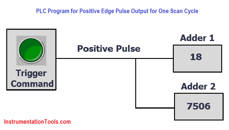
PLC Program for Positive edge pulse output for one scan cycle

Solution

  • We can solve these types of problem by positive edge or rising edge of the digital input.
  • Here we will consider S7-300 PLC for programming, so we can monitor the value and simulate it. We can use PLC SIM for simulation purpose.
  • Here we have considered one simple example. In this example we will consider “Adder 1” register which will add value “1” when transition occurs from 0 to 1 of the trigger command. The register value will be incremented by value 1 after each triggering.
  • For “Adder 2” register, the value will be incremented after receiving the digital input. Here, we are not used the positive edge triggering.

List of Inputs/Outputs

Inputs List

  • Trigger Command : I0.0

Memory Coil

  • Positive Edge of trigger command : M0.0
  • Total Value : MW2
  • Total Value 2 : MW4

PLC Ladder Logic

Network 1:

The initial value of “Adder 1″register is zero. After giving positive edge triggering command for 18 times, the output will be value 18 as it increments by value “1”.
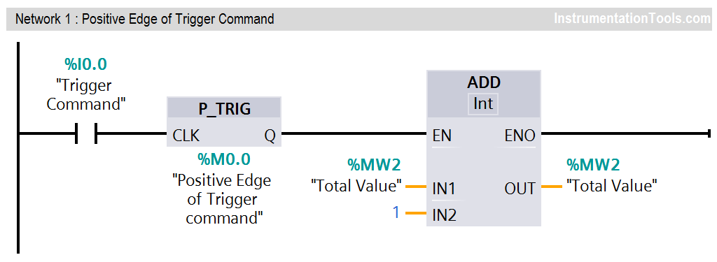
Positive Edge Pulse Output

Simulation (PLCSIM-300) for trigger command with positive edge.

PLC Positive Edge Output

Network 2:

The initial value of “Adder 2″register is zero. After giving triggering command (without positive/negative edge) for 18 times, the output will come some random number (say 7506) instead of value 18 as trigger command directly received.
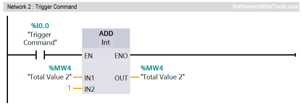
PLC program for positive edge

Simulation (PLCSIM-300) for trigger command without positive edge.

PLC Trigger Command

PLC Logic Description

  • In this application, we have used Siemens S7-300 PLC and TIA Portal Software for programming.
  • Here we have considered two examples for positive edge explanation. Anyone can easily understand the concept.
  • In Network 1, when trigger command (I0.0) is triggered then transition will occur from 0 to 1 and positive pulse instruction will be executed.
  • Say “Adder 1″register will be stored with value “1” in MW0, if trigger command (I0.0) will be triggered then the value will be incremented by “1”.
  • Here for example, we have triggered 18 times when adder 1 is zero, so adder added 18 in total Value (MW0)
  • Another example we have taken in Network 2,  without using positive pulse. so here you can see the result.
  • Say, We have pressed or triggered 18 times but it added 7506 (this is random value it can be different during simulation) in total Value 2 (MW4) so it is not proper addition. Because one pulse have rising or falling edges / positive or negative pulses (o to 1 and 1 to 0).
  • Here also we have used PLC SIM for simulation, so we can simulate the total addition. In first network we have added positive edge so simulator is showing 18. In second network we have added trigger command without positive edge so it is showing some random value.
  • This is the concept of positive edge, we can use this positive edge during any programming application.
  • Above program and simulation is only for explanation purpose and simulation value can be different at simulation time.

Result

PLC Pulse Output

Note: The above PLC Logic provided for basic idea about application of Positive edge trigger command in PLC Logic. The Logic is limited and not complete application.

Author: Bhavesh

If you liked this article, then please subscribe to our YouTube Channel for PLC and SCADA video tutorials.

You can also follow us on Facebook and Twitter to receive daily updates.

Read Next:

  • PLC Program for Mixing Tank
  • Siemens PLC Interview Questions
  • PLC Heat and Bend Glass Tubes
  • Siemens PLC Comparator Logic
  • SLC 500 PLC Programming
Don't Miss Our Updates
Be the first to get exclusive content straight to your email.
We promise not to spam you. You can unsubscribe at any time.
Invalid email address
You've successfully subscribed !

Continue Reading

Data Types in PLC – Bit, Byte, Integer, Real, String
#7 PLC Best Practices – Validate and Alert for Paired Inputs/Outputs
What are Trends in SCADA?
Comparison Instructions in PLC Programming
How to Communicate with Excel from Intouch SCADA?
Why we Require Dual SOV on a Control Valve?
Share This Article
Facebook Whatsapp Whatsapp LinkedIn Copy Link
Share
Leave a Comment

Leave a Reply Cancel reply

Your email address will not be published. Required fields are marked *

Stay Connected

128.3kFollowersLike
69.1kFollowersFollow
210kSubscribersSubscribe
38kFollowersFollow

Categories

Explore More

PLC Programming Example on Bottle Line Control
How to Choose a PLC for New Project? – Criteria for Selection of PLC
How to do Simulation in Schneider PLC?
How to Select a SCADA for New PLC Project?
Normally-open and Normally-closed Switch Contacts
Turbine-Compressor System Architecture
SAVE and BR Memory Instructions in Siemens PLC Programming
What are FIFO and LIFO Sequences in PLC?

Keep Learning

PLC Valve Control Example

Create a Function (FC) for a Valve Logic in Siemens PLC

PLC engineering software

How to Download GX Works? Mitsubishi PLC Software

PLC Fault Diagnosis - PLC Training Documents

PLC Fault Diagnosis – PLC Training Documents

MCQ on PLC (Programmable Logic Controller)

MCQ on PLC (Programmable Logic Controller)

Why Use Normally-Closed Contact for Stop Buttons

Why Use Normally-Closed Contact for Stop Buttons?

Omron PLC for Product Painting with Integrated Weighing System

Omron PLC for Product Painting with Integrated Weighing System

Studio 5000 Logix Emulate

Simulation of Studio 5000 and FactoryTalk View Studio

PLC Multiple Choice Questions

PLC Multiple Choice Questions

Learn More

Remote User Authentication

Security of Industrial Automation Systems

Most Asked Questions on SCADA

Most Asked Questions on SCADA with Answers

Electrical Machines Questions and Answers

Double Excited Magnetic System Quiz

Thermowell Problems

Thermowell Problems

Stability in Frequency Domain

Realization of Basic Compensators

Brix Measurement

Measurement of POL, pH, and BRIX in the Sugar Industry

Safety Instrumented Systems Tutorials

High Reliability of Safety Instrumented Systems

Thermovcouple Circuit

Thermocouple and its Principle

Menu

  • About
  • Privacy Policy
  • Copyright

Quick Links

  • Learn PLC
  • Helping Hand
  • Part Time Job

YouTube Subscribe

Follow US
All rights reserved. Reproduction in whole or in part without written permission is prohibited.
Welcome Back!

Sign in to your account

Username or Email Address
Password

Lost your password?