Inst ToolsInst ToolsInst Tools
  • Ask
  • Courses
  • Videos
  • Q & A
    • Interview
      • Instrumentation
      • Electronics
      • Electrical
      • Practical Questions
    • MCQ
      • Instrumentation MCQ
      • Electrical MCQ
      • Electronics MCQ
      • Control Systems MCQ
      • Analog Electronics MCQ
      • Digital Electronics MCQ
      • Power Electronics MCQ
      • Microprocessor MCQ
      • Multiple Choice Questions
  • EE
    • Electronics
      • Electronics Q & A
      • Electronic Basics
      • Electronic Devices & Circuits
      • Electronics Animation
      • Digital Electronics
    • Electrical
      • Electrical Basics
      • Electrical Q & A
      • Power Electronics
      • Electrical Machines
      • Electrical Animation
      • Power Systems
      • Switchgear & Protection
      • Transmission & Distribution
  • Measure
    • Control Valves
    • Calibration
    • Temperature
    • Pressure
    • Flow
    • Level
    • Analyzers
    • Switches
    • Vibration
    • Solenoid Valve
  • Control
    • PLC Tutorials
    • Control Systems
    • Safety Instrumented System (SIS)
    • Communication
    • Fire & Gas System
  • More
    • Design
    • Tools
    • Animation
    • Basics
    • Formulas
    • Standards
    • TextBooks
    • Common
    • Software
    • Excel Tools
    • Erection & Commissioning
    • Process Fundamentals
    • Videos
    • Books
Search
All rights reserved. Reproduction in whole or in part without written permission is prohibited.
Reading: Paddle Wheel Flow Meters – Principle, Advantages, Limitations
Share
Notification Show More
Font ResizerAa
Inst ToolsInst Tools
Font ResizerAa
  • Courses
  • PLC Tutorials
  • Control Systems
Search
  • Ask
  • Courses
  • Videos
  • Q & A
    • Interview
    • MCQ
  • EE
    • Electronics
    • Electrical
  • Measure
    • Control Valves
    • Calibration
    • Temperature
    • Pressure
    • Flow
    • Level
    • Analyzers
    • Switches
    • Vibration
    • Solenoid Valve
  • Control
    • PLC Tutorials
    • Control Systems
    • Safety Instrumented System (SIS)
    • Communication
    • Fire & Gas System
  • More
    • Design
    • Tools
    • Animation
    • Basics
    • Formulas
    • Standards
    • TextBooks
    • Common
    • Software
    • Excel Tools
    • Erection & Commissioning
    • Process Fundamentals
    • Videos
    • Books
Follow US
All rights reserved. Reproduction in whole or in part without written permission is prohibited.
Inst Tools > Blog > Flow Measurement > Paddle Wheel Flow Meters – Principle, Advantages, Limitations

Paddle Wheel Flow Meters – Principle, Advantages, Limitations

The principle of Paddle Wheel Flow Meters consists of a freely rotating wheel with embedded magnets which is perpendicular to the flow rate.

Last updated: October 31, 2023 11:02 am
Editorial Staff
Flow Measurement How It Works
1 Comment
Share
3 Min Read
SHARE

Paddle wheel flow meters consist of three primary components: the paddle wheel sensor, the pipe fitting, and the display/controller.

Contents
Paddle Wheel Flow MetersAdvantages of Paddle Wheel Flow MeterLimitations of Paddle Wheel Flow Meter

The paddle wheel sensor consists of a freely rotating wheel or impeller with embedded magnets that is perpendicular to the flow and will rotate when inserted in the flowing medium.

Paddle Wheel Flow Meters

Working Principle of Paddle Wheel Flow Meters

As the magnets in the blades spin past the sensor, the paddle wheel meter generates a frequency and voltage signal which is proportional to the flow rate. The faster the flow the higher the frequency and the voltage output.

The paddle wheel meter is designed to be inserted into a pipe fitting, either ‘in-line’ or insertion style. These are available with a wide range of fittings styles, connection methods, and materials such as PVDF, polypropylene, and stainless steel. Similar to turbine meters, the paddle wheel meter requires a minimum run of straight pipe before and after the sensor.

Flow displays and controllers are used to receive the signal from the paddle wheel meter and convert it into actual flow rate or total flow values. The processed signal can be used to control the process, generate an alarm, send signals to external, etc.

Paddle wheel flow meters (also known as Pelton wheel sensors) offer a relatively low-cost, high-accuracy option for many flow system applications, typically with water or water-like fluids.

Advantages of Paddle Wheel Flow Meter

  • Low-cost solution with high flow system accuracy
  • Easy to install and operate, resulting in a low cost of ownership
  • No pressure drop making it ideal for gravity flows
  • Insertion flow meter design lowers installation and maintenance costs

Limitations of Paddle Wheel Flow Meter

  • Paddlewheel meters work best with clean fluids as particulates can prevent the paddle from spinning properly
  • Not suitable for gases
  • Requires a turbulent flow profile (consistent fluid velocity across the pipe diameter) for accuracy
  • Requires a straight run of pipe before and after the flow meter to allow swirl patterns in the flow stream to dissipate
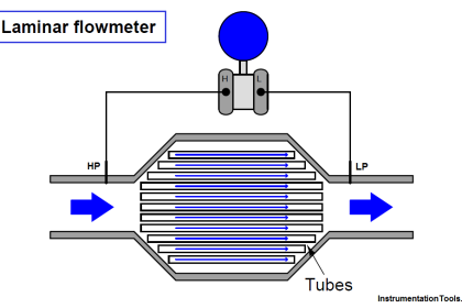
  • Paddlewheel meters may not function properly with high-viscosity fluids where the flow profile is laminar
  • The pipe must be full; any air in the line may lead to inaccuracies

Typical applications for paddle wheel flow meters include the accurate measurement of preset fluid volumes in dispensing systems, control of chemical metering pump output, flow verification, irrigation systems, and alerting users to flow rate increases or decreases outside a programmed range.

If you liked this article, then please subscribe to our YouTube Channel for Instrumentation, Electrical, PLC, and SCADA video tutorials.

You can also follow us on Facebook and Twitter to receive daily updates.

Read Next:

  • Turbine Flow Meter Verification
  • Flow Meter Installation Guide
  • Optical flow meter Principle
  • What is an Ultrasonic Flow Meter?
  • Piston Flow Meters Working
Don't Miss Our Updates
Be the first to get exclusive content straight to your email.
We promise not to spam you. You can unsubscribe at any time.
Invalid email address
You've successfully subscribed !
What is a Velocity-based Flow Meter?
Rotary Abutment Flow Meters Working Principle and Animation
What is a Ultrasonic Flow Meter?
Flow Meter K-factor and Calculations
Difference between Orifice & Restriction Orifice
Share This Article
Facebook Whatsapp Whatsapp LinkedIn Copy Link
Share
1 Comment
  • AYON BHOWMIK says:
    May 30, 2016 at 5:10 pm

    Sir, what is the difference between paddle wheel flow meter and turbine flow meter ? thanks

    Reply

Leave a Reply Cancel reply

Your email address will not be published. Required fields are marked *

Stay Connected

128.3kFollowersLike
69.1kFollowersFollow
208kSubscribersSubscribe
38kFollowersFollow

Categories

Recent Comments

  • Guifty Shimica on Top Non-PLC Certification Courses for Automation Professionals
  • Guifty Shimica on Top Non-PLC Certification Courses for Automation Professionals
  • MIHARITSOA Aina Sitraka on Top Non-PLC Certification Courses for Automation Professionals
  • Vaishnavi on Free Instrumentation Course for Trainee Engineers

Related Articles

DP transmitter

Square-root characteristics of Differential Pressure Flow Meters

L2F insertion-style flowmeter

Optical Flow Meter Principle

rangeability-of-flow-meter-vs-percentage-of-maximum-flow

Flow Transmitter Rangeability

Solenoid-Valve-Working-Animation

Solenoid Valve Working Animation

Ultrasonic Flowmeters Principle

Factors Affecting the Performance of Ultrasonic Flow Meters

Averaging Pitot Tube Principle

What is a Torbar? – Averaging Pitot Tubes

Metal tube Variable Area Flowmeters Principle

Metal Tube Variable Area Flow Meters Principle

RTD lead resistances Wiring

Resistance Temperature Detectors Working Principle

More Articles

Statement List (STL) to Find Highest Value in the Data Block

Statement List (STL) to Find Highest Value

trip solenoid installed on a control valve appears

SIS Final Control Elements

Thermocouple Extension Lead Problem

Thermocouple Extension Lead Problem

RTD Measuring with three leads

How 3 Wire RTD Lead Wire Resistance Eliminated?

Parallel Open Circuit Fault

Parallel Open Circuit Faults

Typical Switchyard Layout

Electrical Substation – Busbar Arrangements and Layouts

RC snubber circuits

How Snubber Circuit works ?

Types of Script in Intouch Scada

Types of Script in Intouch Scada

Follow US
All rights reserved. Reproduction in whole or in part without written permission is prohibited.
Welcome Back!

Sign in to your account

Username or Email Address
Password

Lost your password?