The transmit time flow meter sends and receives the ultrasonic waves between transducers in both the upstream and downstream directions in the pipe.
Transit Time Flow Meter
At no flow conditions, It takes the same time to travel upstream and downstream between the transducers. Under flowing conditions, The upstream wave will travel slower and take more time than the downstream wave.
When the fluid moves faster, The difference between the upstream and downstream time increases. The difference in transit times in the upstream and downstream directions(Tu-Td) measured over the same path can be used to calculate the flow passing through a pipe.
Transmit time ultrasonic flow meters are more accurate and economical than the doppler ultrasonic flow meters.
Types of Transit Time Flow Meters
Different Types of Transmit time flow meters are available based on their installation.
They are
- V – Type Transmit time flow meters
- Z – Type Transmit time flow meters
- W – Type Transmit time flow meters
V – Type Transmit time flow meters
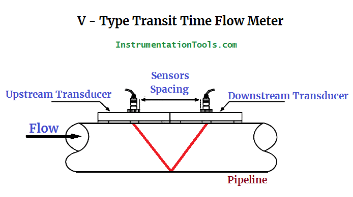
The two sensors are installed on a pipeline such that the ultrasonic waves travel in the form of v-shape, hence called them as V-Type Transmit time flow meters, as shown in below figure.
Z – Type Transmit time flow meters
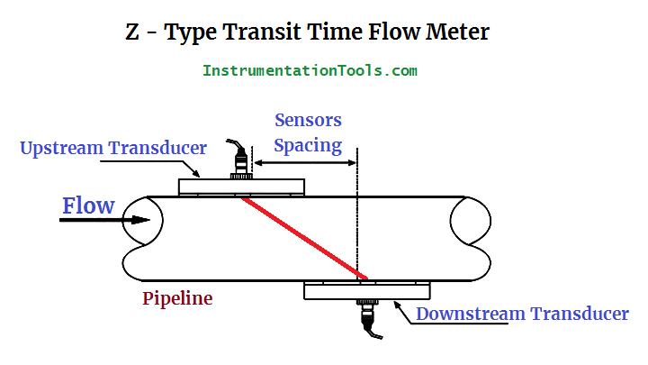
The two sensors are installed on a pipeline such that the ultrasonic waves travel in the form of z-shape, hence called them as Z-Type Transmit time flow meters, as shown in below figure.
W – Type Transmit time flow meters
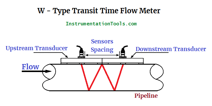
The two sensors are installed on a pipeline such that the ultrasonic waves travel in the form of w-shape, hence called them as W-Type Transmit time flow meters, as shown in below figure.
Advantages of Transit Time Flow Meters
The main advantage of the transit time flow meter is, that it works non-invasively with clean and ultra-pure fluids.
This allows the user to maintain the integrity of the fluid while still measuring the flow.
Some of the other advantages include:
- Easy installation-transducer set clamps onto pipe.
- No moving parts to wear out.
- Zero pressure drop.
- Works well with clean and ultrapure fluids.
- No leakage potential.
- Insensitive to liquid temperature, viscosity, density or pressure variations.
Disadvantages of Transit Time Flow Meters
The transit time flow meter performance can suffer from pipe-wall interference, accuracy and repeatability problems can result if there is any Space Gap between the fluid and pipe wall.
The transit time flow meters will not operate on dirty, bubbly, particulate-ladden fluids. Sometimes, the purity of a fluid may fluctuate so as to effect the accuracy of the flow measurement.
For such cases, there are Hybrid meters on the market that will access the fluid conditions within the pipe and automatically choose doppler or transit time meter operations where needed.
Applications of Transit Time Flow Meter
Transit time flow meter have wide applicability for flow measurement of clean or ultra-pure streams.
Some of the applications include:
- Clean water flow rate in water treatment plants.
- Hot or cold water in power plants.
- Pure and ultra-pure fluids in pharmaceutical, food and beverage industries.
- Liquid to medium crude oils in the petroleum refining industry.
- Water distribution systems used in agriculture and irrigation.
If you liked this article, then please subscribe to our YouTube Channel for Instrumentation, Electrical, PLC, and SCADA video tutorials.
You can also follow us on Facebook and Twitter to receive daily updates.
Read Next:
- Flow Meter Turndown Ratio
- Ultrasonic Flow Meter Performance
- Flow Meter K-factor Calculation
- Turbine Flow Meter Installation
- Flow Measurement Questions





The transit time ultrasonic flow meter has three possible transducer configurations: Z, V and W. All are recognized as a single measuring path, whereas the ultrasonic beam follows a single path.
In all three configurations, the output produced by the transducers is converted to a current, frequency or voltage signal. The preferred configuration is determined by factors such as:
The characteristics of the flowing liquid
In the “Z” configuration, the transducers are positioned on opposite sides of the pipe with one downstream from the other. Usually, the distance downstream is approximately D/2, where D equals the diameter of the pipe. The optimum distance is calculated by a converter. This arrangement is only advisable under conditions where there is limited space, high turbidity, a mortar lining or a thick build-up of scale on the interior walls of the pipe. It should be avoided for installations on small pipes, where the accuracy of its measurements tends to degrade.
The “V” configuration is recommended for most installations. This arrangement places the two transducers on the same side of the pipe within approximately a diameter of the pipe from each other. A rail attachment clamps on the pipe and allows the transducers to be slid horizontally to position them the calculated distance apart.
A “W” configuration is most often used for installations on pipes with diameters of ½ inch to 1½ inches. In this arrangement, the ultrasonic signal rebounds from the wall three times; therefore, it must travel a greater distance. High turbidity liquids, and scale or deposit build-up on the interior of the pipe wall can diminish accuracy.
reference – omega