Inst ToolsInst ToolsInst Tools
  • Courses
  • Automation
    • PLC
    • Control System
    • Safety System
    • Communication
    • Fire & Gas System
  • Instrumentation
    • Design
    • Pressure
    • Temperature
    • Flow
    • Level
    • Vibration
    • Analyzer
    • Control Valve
    • Switch
    • Calibration
    • Erection & Commissioning
  • Interview
    • Instrumentation
    • Electrical
    • Electronics
    • Practical
  • Q&A
    • Instrumentation
    • Control System
    • Electrical
    • Electronics
    • Analog Electronics
    • Digital Electronics
    • Power Electronics
    • Microprocessor
  • Request
Search
  • Books
  • Software
  • Projects
  • Process
  • Tools
  • Basics
  • Formula
  • Power Plant
  • Root Cause Analysis
  • Electrical Basics
  • Animation
  • Standards
  • 4-20 mA Course
  • Siemens PLC Course
Reading: Displacer Level Transmitter Working Principle
Share
Notification Show More
Font ResizerAa
Inst ToolsInst Tools
Font ResizerAa
  • Courses
  • Design
  • PLC
  • Interview
  • Control System
Search
  • Courses
  • Automation
    • PLC
    • Control System
    • Safety System
    • Communication
    • Fire & Gas System
  • Instrumentation
    • Design
    • Pressure
    • Temperature
    • Flow
    • Level
    • Vibration
    • Analyzer
    • Control Valve
    • Switch
    • Calibration
    • Erection & Commissioning
  • Interview
    • Instrumentation
    • Electrical
    • Electronics
    • Practical
  • Q&A
    • Instrumentation
    • Control System
    • Electrical
    • Electronics
    • Analog Electronics
    • Digital Electronics
    • Power Electronics
    • Microprocessor
  • Request
Follow US
All rights reserved. Reproduction in whole or in part without written permission is prohibited.
Inst Tools > Blog > Level Measurement > Displacer Level Transmitter Working Principle

Displacer Level Transmitter Working Principle

Last updated: September 20, 2017 9:12 am
Editorial Staff
Level Measurement
4 Comments
Share
3 Min Read
SHARE

Displacer Level Transmitter Intrenal Diagram

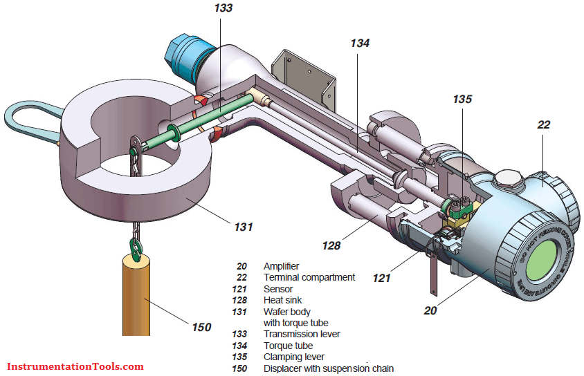
The buoyancy force of the displacer is transferred via transmission lever and torque tube to operating rod of the sensor, where it acts on free end of sensor element.Four thin film metal strain gauge elements are sputtered onto sensor element, which change their resistance in the ratio of the tensile or pressure tension. These four thin film metal strain gauge elements are connected as a Wheatstone full bridge supplied from amplifier.

The voltage at the diagonal bridge section which is proportional to the effective weight is fed to the electronic amplifier as an input signal. This voltage is converted via the electronic amplifier into the 4 to 20 mA or digital two-wire output signal. The amplifier is supplied by the signal current circuit in two wire mode.
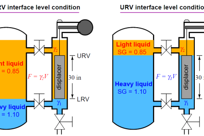
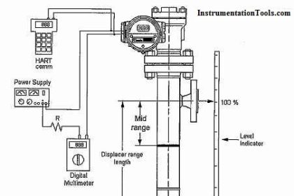
displacer-level-transmitter-calibration

CALIBRATION:

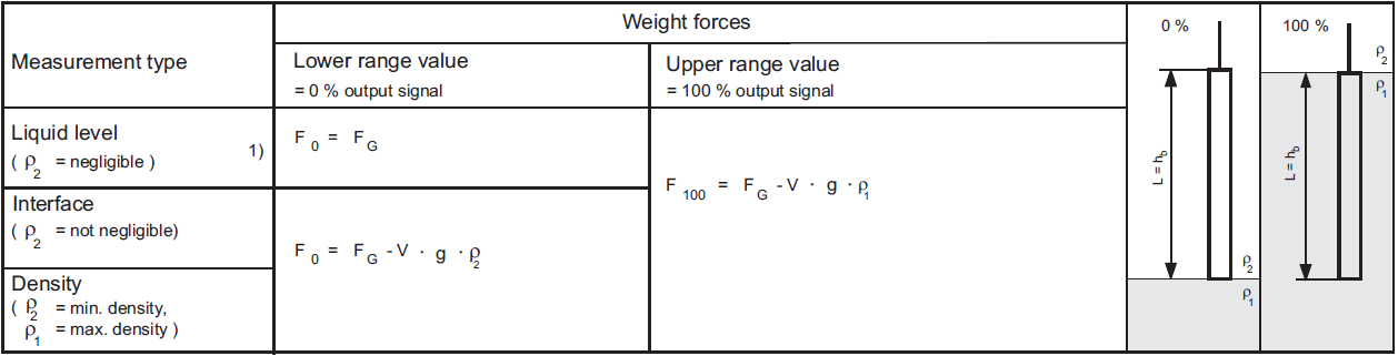
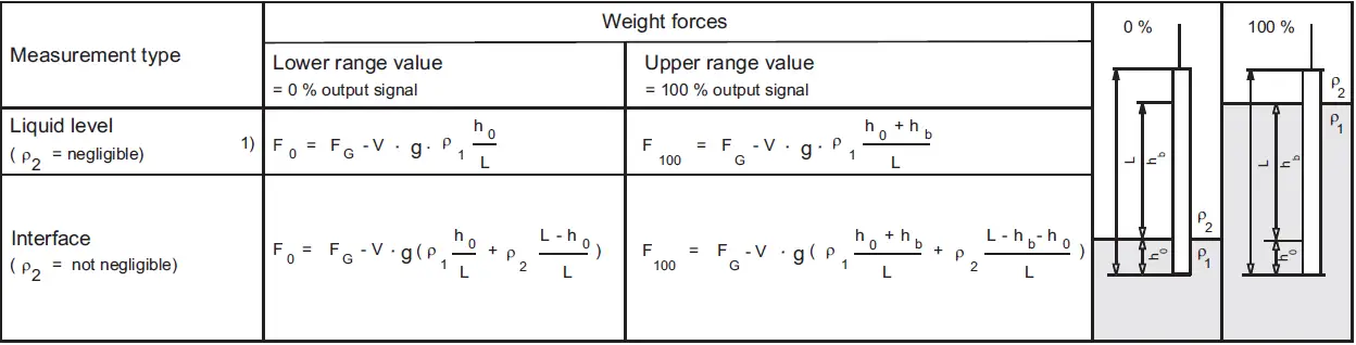
CALCULATING WEIGHT FORCES: For LRV & URV of Displacer Level Transmitter

Displacer length = measuring range

Displacer Level Transmitter

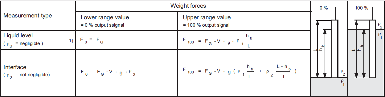
Displacer length > measuring range (without elevation)

Displacer Level Transmitter Calibration

Displacer length > measuring range (with elevation)

Displacer Level Transmitter Calibration Formula

Displacer Level Transmitter Equations

Downlaod Displacer Level Transmitter Formula

Measuring span
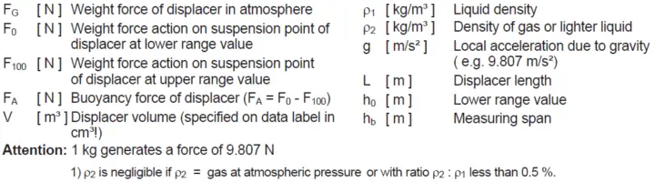
The transmitter is designed for a buoyancy force measuring span of minimum force to maximum force in N.

Weight force

The maximum weight of the displacer FG max  for level measurements. For density or interface measurements, the displacer must be dimensioned so that after deducting FA of the lighter process media, the remaining force F0 does not exceed FG max.

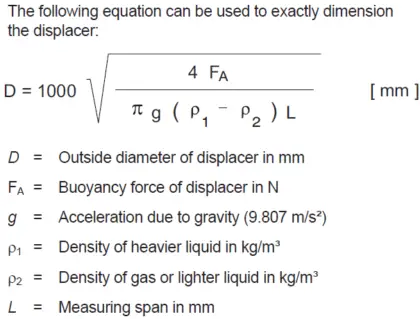
Determining displacer diameters
For optimum use of the transmitter, the displacer should be dimensioned so that the greatest possible buoyancy force is generated over the measuring range. On the other hand, the maximum possible diameter of the displacer must be taken into consideration. In the above graph the displacer diameter can easily be estimated dependent on the measuring span and the buoyancy force.
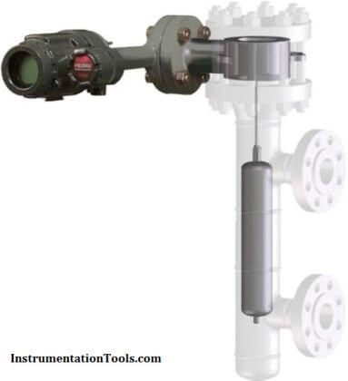
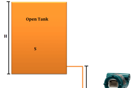
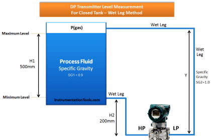
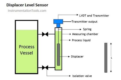
Displacer Level Formula

Measuring principle
Any body immersed into a liquid is subject to buoyancy force which depends on the liquid density. This is exploited to determine liquid level, density and interface level by suspending a displacer with constant cylindric shape into a liquid. Changes in buoyancy forces are proportional to liquid level changes and are converted to a measuring signal. The displacer is fully immersed for density and interface level detection.

Also Read: Zero Suppression & Zero Elevation

Don't Miss Our Updates
Be the first to get exclusive content straight to your email.
We promise not to spam you. You can unsubscribe at any time.
Invalid email address
You've successfully subscribed !

Continue Reading

Ultrasonic Level Transmitter Animation
Level Gauge Interface & Temperature Problems
Basics of Level Measurement
Non-Contacting Radar Level Transmitter Working Principle
Basics of Sight Glass Level Gauge
Basics of Differential Pressure Level Transmitters
Share This Article
Facebook Whatsapp Whatsapp LinkedIn Copy Link
Share
4 Comments
  • Mohammed Abdelhadi says:
    July 15, 2016 at 1:36 pm

    Thanks so much

    Reply
  • Shovan kumar Nayak says:
    December 18, 2016 at 10:44 am

    Thank You for the information Sir,i really like the blog you have posted,really meaningful.

    Reply
  • ahmed messallam says:
    April 11, 2017 at 1:44 pm

    valuable information for different types of instrumentation, thank you in advance.

    Reply
  • Ganeah Mirkale says:
    May 19, 2017 at 1:32 pm

    What is calibration procedure of bubblers type level transmitter

    Reply

Leave a Reply Cancel reply

Your email address will not be published. Required fields are marked *

Stay Connected

128.3kFollowersLike
69.1kFollowersFollow
210kSubscribersSubscribe
38kFollowersFollow

Categories

Explore More

Hydrostatic Level Measurement
DP Level Transmitter with Zero Suppression Calibration
Types of Industrial Level Sensors
Torque Tube Level Measurement Principle
Magnetic Level Indicator Principle, Limitations, Installation and Calibration
Pressure Transmitters Leg Compensation Technique
Laser Level Measurement Principle
Root Cause Analysis of Differential Pressure Level Transmitter

Keep Learning

Boiler-Drum-Level-transmitter-calibration

Boiler Drum Level Transmitter Calibration

Capillary Remote Seal Leave Measurement

Siemens Pressure Transmitter with Remote Seals Calculations

Calibration Procedure of displacer type Level transmitter

Calibration of Displacer Level Transmitter

Float Level Switch Principle

Float Level Switch Working Principle Animation

Hydrostatic pressure Measurement

Basics of Hydrostatic Level Measurement

Installation and Calibration of Level Transmitter

Installation and Calibration of Level Transmitter

Tank Gauging Measurement

Purpose of Tank Gauging Level Measurement

Displacer Level Sensor Working Animation

Displacer Level Sensor Working Animation

Learn More

Actuator Sensor Interface (ASi) Protocol in PLC

Actuator Sensor Interface (ASi) Protocol in PLC

Hydrostatic level transmitter Formula

Hydrostatic Level Transmitter Questions

Thermal Dispersion Flow Switch Working Principle

Thermal Dispersion Flow Switch Working Principle

Root Locus Concepts Objective Questions

Root Locus in Control Systems

PLC Karnaugh maps

How to Simplify PLC Coding Using Karnaugh Maps?

Slop Tank Level Transmitter Erection

Wrong Installation of Horn Type Radar Level Transmitter on Sloping Tank

cable-trays-glossary

Cable Trays Glossary

oxygen Safety Analyzer

Oxygen Safety Analyzer

Menu

  • About
  • Privacy Policy
  • Copyright

Quick Links

  • Learn PLC
  • Helping Hand
  • Part Time Job

YouTube Subscribe

Follow US
All rights reserved. Reproduction in whole or in part without written permission is prohibited.
Welcome Back!

Sign in to your account

Username or Email Address
Password

Lost your password?