Inst ToolsInst ToolsInst Tools
  • Courses
  • Videos
  • Q & A
    • Interview
      • Instrumentation
      • Electronics
      • Electrical
      • Practical Questions
    • MCQ
      • Instrumentation MCQ
      • Electrical MCQ
      • Electronics MCQ
      • Control Systems MCQ
      • Analog Electronics MCQ
      • Digital Electronics MCQ
      • Power Electronics MCQ
      • Microprocessor MCQ
      • Multiple Choice Questions
  • EE
    • Electronics
      • Electronics Q & A
      • Electronic Basics
      • Electronic Devices & Circuits
      • Electronics Animation
      • Digital Electronics
    • Electrical
      • Electrical Basics
      • Electrical Q & A
      • Power Electronics
      • Electrical Machines
      • Electrical Animation
      • Power Systems
      • Switchgear & Protection
      • Transmission & Distribution
  • Measure
    • Control Valves
    • Calibration
    • Temperature
    • Pressure
    • Flow
    • Level
    • Analyzers
    • Switches
    • Vibration
    • Solenoid Valve
  • Control
    • PLC Tutorials
    • Control Systems
    • Safety Instrumented System (SIS)
    • Communication
    • Fire & Gas System
  • More
    • Design
    • Tools
    • Animation
    • Basics
    • Formulas
    • Standards
    • TextBooks
    • Common
    • Software
    • Excel Tools
    • Erection & Commissioning
    • Process Fundamentals
    • Videos
    • Books
Search
All rights reserved. Reproduction in whole or in part without written permission is prohibited.
Reading: SIS – Safety Instrumented System Example
Share
Notification Show More
Font ResizerAa
Inst ToolsInst Tools
Font ResizerAa
  • Courses
  • PLC Tutorials
  • Control Systems
Search
  • Courses
  • Videos
  • Q & A
    • Interview
    • MCQ
  • EE
    • Electronics
    • Electrical
  • Measure
    • Control Valves
    • Calibration
    • Temperature
    • Pressure
    • Flow
    • Level
    • Analyzers
    • Switches
    • Vibration
    • Solenoid Valve
  • Control
    • PLC Tutorials
    • Control Systems
    • Safety Instrumented System (SIS)
    • Communication
    • Fire & Gas System
  • More
    • Design
    • Tools
    • Animation
    • Basics
    • Formulas
    • Standards
    • TextBooks
    • Common
    • Software
    • Excel Tools
    • Erection & Commissioning
    • Process Fundamentals
    • Videos
    • Books
Follow US
All rights reserved. Reproduction in whole or in part without written permission is prohibited.
Inst Tools > Blog > Safety Instrumented System (SIS) > SIS – Safety Instrumented System Example

SIS – Safety Instrumented System Example

Last updated: March 22, 2019 10:55 am
Editorial Staff
Safety Instrumented System (SIS)
No Comments
Share
6 Min Read
SHARE

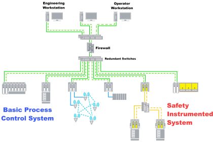
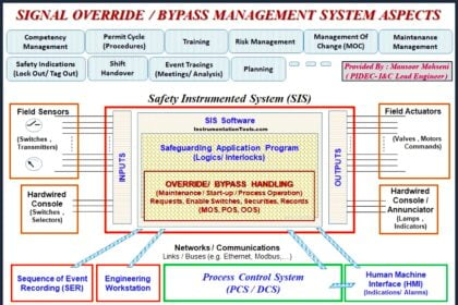
A Safety instrumented system (SIS) consists of an engineered set of hardware and software controls which are especially used on critical process systems.

Contents
SIS – Safety Instrumented System ExampleSIS example : Water Treatment Oxygen Purge System

SIS – Safety Instrumented System Example

Examples of Safety instrumented systems are most often used in process (e.g., refineries, chemical, nuclear) facilities to provide protection such as:

  • High fuel gas pressure initiates action to close the main fuel gas valve.
  • High reactor temperature initiates action to open cooling media valve.
  • High distillation column pressure initiates action to open a pressure vent valve.

Another example of SIS is for water treatment facility, described as below :

One of the processes of municipal wastewater treatment is the aerobic digestion of organic matter by bacteria.

This process emulates one of many waste-decomposition processes in nature, performed on an accelerated time frame for the needs of large wastewater volumes in cities.

The process consists of supplying naturally occurring bacteria within the wastewater with enough oxygen to metabolize the organic waste matter, which to the bacteria is food.

In some treatment facilities, this aeration is performed with ambient air. In other facilities, it is performed with nearly pure oxygen.

Aerobic decomposition is usually part of a larger process called activated sludge, whereby the effluent from the decomposition process is separated into solids (sludge) and liquid (supernatant), with a large fraction of the sludge recycled back to the aerobic chamber to sustain a healthy culture of bacteria and also ensure adequate retention time for decomposition to occur.

Separating liquids from solids and recycling the solids ensures a short retention time for the liquid (allowing high processing rates) and a long retention time for the solids (ensuring thorough digestion of organic matter by the bacteria).

SIS example : Water Treatment Oxygen Purge System

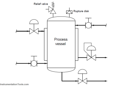
A simplified P&ID of an activated sludge water treatment system is shown here, showing how both the oxygen flow into the aeration chamber and the sludge recycle flow back to the aeration chamber are controlled as a function of influent wastewater flow:

water treatment plant P&ID

Aerobic decomposition performed with ambient air as the oxidizer is a very simple and safe process. Pure oxygen may be chosen instead of ambient air because it accelerates the metabolism of the bacteria, allowing more processing flow capacity in less physical space.

For the same reason that pure oxygen accelerates bacterial metabolism, it also accelerates combustion of any flammable substances. This means if ever a flammable vapor or liquid were to enter the aeration chamber, there would be a risk of explosion.

Although flammable liquids are not a normal component of municipal wastewater, it is possible for flammable liquids to find their way to the wastewater treatment plant.

One possibility is the event of a fuel carrier vehicle spilling its cargo, with gasoline or some other volatile fuel draining into a sewer system tunnel through holes in a grate.

Such an occurrence is not normal, but certainly possible. Furthermore, it may occur without warning for the operations personnel to take preemptive action at the wastewater treatment plant.

To decrease this safety hazard, Low Explosive Limit (LEL) sensors installed on the aeration chamber detect and signal the presence of flammable gases or vapors inside the chamber.

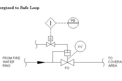
If any of the sensors register the presence of flammable substances, a safety shutdown system purges the chamber of pure oxygen by taking the following steps:

  • Stop the flow of pure oxygen into the aeration chamber
  • Open large vent valves to atmosphere
  • Start air blowers to purge the chamber of residual pure oxygen

safety shutdown system P&ID

As with the P&ID, this diagram is a simplified representation of the real safety shutdown system.

In a real system, multiple analytical high-alarm (LEL) sensors work to detect the presence of flammable gases or vapors, and the oxygen block valve arrangement would most likely be a double block and bleed rather than a single block valve.

The following photograph shows an LEL sensor mounted inside an insulated enclosure for protection from cold weather conditions at a wastewater treatment facility:

LEL sensor

In this photograph, we see a purge air blower used to sweep the aeration chamber of pure oxygen (replacing it with ambient air) during an emergency shutdown condition:

purge air blower

Since this is a centrifugal blower, providing no seal against air flow through it when stopped, an automatic purge valve located downstream (not to be confused with the manually-actuated vent valve seen in this photograph) is installed to block off the blower from the oxygen-filled chamber.

This purge valve remains shut during normal operation, and opens only after the blower has started to initiate a purge.

Articles You May Like :

What is a Shutdown Valve ?

Safety Integrity Level (SIL)

SIS Logic Solvers

SIS Interview Questions

S84 / IEC 61511 Standard

Don't Miss Our Updates
Be the first to get exclusive content straight to your email.
We promise not to spam you. You can unsubscribe at any time.
Invalid email address
You've successfully subscribed !

Continue Reading

Failure rate and MTBF of Safety Instrumented Systems
What is HIPPS System in Oil and Gas?
SIS Bypass and Impairment – Safety Instrumented System
Component De-rating in Control Systems
ESDV : How it Works ?
SIS Hardware Fault Tolerance – Methods to Overcome HFT issues
Share This Article
Facebook Whatsapp Whatsapp LinkedIn Copy Link
Share
Leave a Comment

Leave a Reply Cancel reply

Your email address will not be published. Required fields are marked *

Stay Connected

128.3kFollowersLike
69.1kFollowersFollow
208kSubscribersSubscribe
38kFollowersFollow

Categories

Explore More

Safety Instrumented Burner Management System
SIS Example : Nuclear Reactor Controls
SIS Testing and Repair Deferral
Understanding Emergency Shutdown Button Installation (ESD)
Difference between Availability, Reliability & SIL
SIS Maintenance – Safety Instrumented System
Test Questions on Safety Instrumented System
Safety Instrumented System Handbook – SIS Tutorials

Keep Learning

SIS Application Program - Safety Instrumented System

SIS Application Program – Safety Instrumented System

Smart Valve Monitoring

SIS Instruments and Valves Inline Testing – Safety Instrumented System

BPCS Control System and ESD Safety System of Delta-V DCS

BPCS Control System and ESD Safety System of Delta-V DCS

SIS Verification & Validation - Safety Instrumented System

SIS Verification & Validation – Safety Instrumented System

SIS PFD - Safety Instrumented System

SIS PFD – Safety Instrumented System

level of liquid inside a vessel

Concept of Redundancy in Control Systems

SIS Failures and Reliability - Safety Instrumented Systems

SIS Failures and Reliability – Safety Instrumented Systems

safety PLC programming

SIS Logic Solver

Go Deeper

pH Analyzers Questions and Answers

Combination Electrode Questions & Answers

Single-beam non-dispersive analyzer

Single-beam Non-dispersive Analyzer

AC Induction Motor Construction

Basics of AC Induction Motors

Common Questions on Oil and Natural Gas Industry

Common Questions on Oil and Natural Gas Industry

Functions of Rupture Disc

Why is a Rupture Disc Required? – Functions & Selections

Nuclear Plant Sensors and Detectors Quiz

Nuclear Plant Sensors and Detectors Quiz

PLC Water Project

Smart Spray System using Wecon PLC

PLC Programmer Unknown Do's

Unknown Do’s Need to Know as a PLC Programmer

Follow US
All rights reserved. Reproduction in whole or in part without written permission is prohibited.
Welcome Back!

Sign in to your account

Username or Email Address
Password

Lost your password?