Inst ToolsInst ToolsInst Tools
  • Courses
  • Videos
  • Q & A
    • Interview
      • Instrumentation
      • Electronics
      • Electrical
      • Practical Questions
    • MCQ
      • Instrumentation MCQ
      • Electrical MCQ
      • Electronics MCQ
      • Control Systems MCQ
      • Analog Electronics MCQ
      • Digital Electronics MCQ
      • Power Electronics MCQ
      • Microprocessor MCQ
      • Multiple Choice Questions
  • EE
    • Electronics
      • Electronics Q & A
      • Electronic Basics
      • Electronic Devices & Circuits
      • Electronics Animation
      • Digital Electronics
    • Electrical
      • Electrical Basics
      • Electrical Q & A
      • Power Electronics
      • Electrical Machines
      • Electrical Animation
      • Power Systems
      • Switchgear & Protection
      • Transmission & Distribution
  • Measure
    • Control Valves
    • Calibration
    • Temperature
    • Pressure
    • Flow
    • Level
    • Analyzers
    • Switches
    • Vibration
    • Solenoid Valve
  • Control
    • PLC Tutorials
    • Control Systems
    • Safety Instrumented System (SIS)
    • Communication
    • Fire & Gas System
  • More
    • Design
    • Tools
    • Animation
    • Basics
    • Formulas
    • Standards
    • TextBooks
    • Common
    • Software
    • Excel Tools
    • Erection & Commissioning
    • Process Fundamentals
    • Videos
    • Books
Search
All rights reserved. Reproduction in whole or in part without written permission is prohibited.
Reading: Thermocouples Green Rot Effect
Share
Notification Show More
Font ResizerAa
Inst ToolsInst Tools
Font ResizerAa
  • Courses
  • PLC Tutorials
  • Control Systems
Search
  • Courses
  • Videos
  • Q & A
    • Interview
    • MCQ
  • EE
    • Electronics
    • Electrical
  • Measure
    • Control Valves
    • Calibration
    • Temperature
    • Pressure
    • Flow
    • Level
    • Analyzers
    • Switches
    • Vibration
    • Solenoid Valve
  • Control
    • PLC Tutorials
    • Control Systems
    • Safety Instrumented System (SIS)
    • Communication
    • Fire & Gas System
  • More
    • Design
    • Tools
    • Animation
    • Basics
    • Formulas
    • Standards
    • TextBooks
    • Common
    • Software
    • Excel Tools
    • Erection & Commissioning
    • Process Fundamentals
    • Videos
    • Books
Follow US
All rights reserved. Reproduction in whole or in part without written permission is prohibited.
Inst Tools > Blog > Temperature Measurement > Thermocouples Green Rot Effect

Thermocouples Green Rot Effect

Last updated: November 20, 2019 3:27 pm
Editorial Staff
Temperature Measurement
No Comments
Share
5 Min Read
SHARE

Thermocouples Green Rot Effect

Type “K” thermocouples are widely used for temperature measurement and control up to about 2000 Deg F. They operate very well in oxidizing atmospheres.

Contents
Thermocouples Green Rot EffectType K ThermocoupleType N Thermocouple

However, if a reducing gas (such as hydrogen) is present, a reducing atmosphere can come in contact with the wires. Under these conditions, with only a very small amount of oxygen present, the chromium in the chromel alloy oxidizes. This reduces the emf output and the thermocouple reads low temperature reading. This phenomenon is known as “green rot,” due to the color of the affected alloy.

Although not always distinctively green, the chromel wire will develop a mottled silvery skin and become magnetic. An easy way to check for this problem is to see if the two wires are magnetic. (Normally, chromel is non-magnetic.)

Hydrogen in the atmosphere is the usual cause of green rot. At high temperatures, it can diffuse through solid metals or an intact metal thermowell. Even the sheath of a magnesium oxide insulated thermocouple will not keep the hydrogen out.

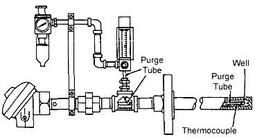
To overcome this problem, a “purged” thermowell is used. Here, a flow of air is brought down through a small tube inside the thermowell to sweep out any hydrogen which has entered the well. (See Below Figure) The small air flow becomes heated on its way down the tube, so it doesn’t chill the sensing junction.

thermocouple installation

Fig : Installation of a purge tube allows air to be introduced into the thermowell. The air eliminates hydrogen that has entered the well and which would create a reducing atmosphere around the thermocouple.

Type K Thermocouple

The Type K thermocouple is composed of a Nickel-10% chromium (+) wire versus a nickel-5% aluminum and silicon (-) wire. This type of thermocouple should only be used in oxidizing or inert atmospheres with a service temperature range between -200°C and 1260°C (-330°F to 2300°F). They are most widely used at temperatures above 540’C (1000″F) due to superior oxidation resistance in comparison to Types E, T, or J.

There are some conditions which should be avoided when using Type K thermocouples. Vacuum applications should not use Type K due to vaporization of chromium in the positive element. Type K thermocouples should not be used in Sulfurous environments since both elements will rapidly corrode and the negative element will eventually fail mechanically due to becoming brittle. Reducing atmospheres should also be avoided.

Low oxygen levels can cause the Green-Rot phenomenon in which the chromium in the elements starts to oxidize causing large negative drifts in calibration. Green-Rot is most pronounced when the thermocouples are used between 815°C to 1040°C (1500°F to 1900°F).

ln order to avoid this problem, large lD protection tubes should be used to maximize internal air circulation or the installation of an oxygen getter in the bottom of the protection tube. lf Green-Rot is a serious problem, Type N thermocouples should be installed.

The negative element, or KN, of a Type K thermocouple can be described by any of the following names: Alumel2, HAI-KN1, ThermoKanthal-KNs, T-2s, Nickel-silicon, or Nial+. The positive element, or KP, of a Type K thermocouple can be described by the following names: Chromel2, Tophel+, ThermoKanthal-KPs, Nickel-chrome, T-13, or HAI-KP1.

Type N Thermocouple

The Type N thermocouple is composed of a nickel-14% chromium-1 1/2% silicon (+) wire versus a nickel 4 1/2% silicon-1/10% magnesium (-) wire. The Type N thermocouple is the newest addition to the ISA family.

lt was developed to be used under the same conditions as a Type K. Type N should be used in oxidizing or inert atmospheres with a service temperature range between -200°C and 1260°C (-330°F to 2300°F).

The addition of silicon and chromium makes this type of thermocouple more resistant to Green-Rot and less drifting when compared to a Type K. The negative element, or NN, of a Type N thermocouple can be described by any of the following names: Nisil, nickel-silicon, or, HAI-NN1. The positive element, or NP, of a Type N thermocouple can be described by any of the following names: Nicrosil, nickel-chromium- silicon, or HAI-NP1 .

Sources : asrichards.com transcat.com
Don't Miss Our Updates
Be the first to get exclusive content straight to your email.
We promise not to spam you. You can unsubscribe at any time.
Invalid email address
You've successfully subscribed !

Continue Reading

Response Time Test of RTD and Thermocouple
Why we use Wheatstone bridge in RTD?
Effect of Lead Wire Resistance on RTD
Pyrometers Handbook
Thermocouple Details
Temperature Switch Working Principle
Share This Article
Facebook Whatsapp Whatsapp LinkedIn Copy Link
Share
Leave a Comment

Leave a Reply Cancel reply

Your email address will not be published. Required fields are marked *

Stay Connected

128.3kFollowersLike
69.1kFollowersFollow
208kSubscribersSubscribe
38kFollowersFollow

Categories

Explore More

Thermocouple and its Principle
Types of Thermowells
Functions of Temperature Detectors
RTD Sensor Connections
What to Choose RTD or Thermocouple ?
Calculate Temperature Coefficient of RTD
Different Types of Thermometers
Thermocouple Software compensation
Thermowell Outer Diameter Larger than Nozzle Inside Diameter?
Calibration of Pyrometers using Black Body

Keep Learning

RTD with Thermowell

Temperature Sensor Accessories

Two Wire RTD Lead Wire Resistance Error

Temperature Error of 2-Wire, 3-Wire & 4-Wire RTD

Three Wire RTD Temperature Compensation

Ambient Temperature Effects on RTD

Temperature Transmitter Foundation Fieldbus Configuration

Foundation Fieldbus Temperature Transmitter Configuration

thermocouple types

What is a Thermocouple ?

RTD Construction

Introduction to RTDs

RTD and Thermocouple Testing

Temperature Transmitter Preventive Maintenance

thermocouple voltages

Manually Interpreting Thermocouple Voltages

Discover More

P&ID arrangement for Control Valves

P&ID Guidelines for Control Valves

Weigh feeders Principle

What is a Weigh Feeder?

Top 250 Digital Circuits Objective Questions and Answers

Top 250 Digital Circuits Objective Questions and Answers

Vibration Sensors Theory

How Vibration sensors Work ?

Establish Communication Between Two PLC Via PROFIBUS Protocol

Establish Communication Between Two PLC Via PROFIBUS Protocol

Linear Heat Detector Working Principle

What are Linear Heat Detectors?

HAZOP

What is HAZOP ?

Level Transmitter trend

Identify Level Control Loop Tuning Problems

Follow US
All rights reserved. Reproduction in whole or in part without written permission is prohibited.
Welcome Back!

Sign in to your account

Username or Email Address
Password

Lost your password?