Inst ToolsInst ToolsInst Tools
  • Courses
  • Automation
    • PLC
    • Control System
    • Safety System
    • Communication
    • Fire & Gas System
  • Instrumentation
    • Design
    • Pressure
    • Temperature
    • Flow
    • Level
    • Vibration
    • Analyzer
    • Control Valve
    • Switch
    • Calibration
    • Erection & Commissioning
  • Interview
    • Instrumentation
    • Electrical
    • Electronics
    • Practical
  • Q&A
    • Instrumentation
    • Control System
    • Electrical
    • Electronics
    • Analog Electronics
    • Digital Electronics
    • Power Electronics
    • Microprocessor
  • Request
Search
  • Books
  • Software
  • Projects
  • Process
  • Tools
  • Basics
  • Formula
  • Power Plant
  • Root Cause Analysis
  • Electrical Basics
  • Animation
  • Standards
  • 4-20 mA Course
  • Siemens PLC Course
Reading: What is Ladder Diagram Programming ?
Share
Notification Show More
Font ResizerAa
Inst ToolsInst Tools
Font ResizerAa
  • Courses
  • Design
  • PLC
  • Interview
  • Control System
Search
  • Courses
  • Automation
    • PLC
    • Control System
    • Safety System
    • Communication
    • Fire & Gas System
  • Instrumentation
    • Design
    • Pressure
    • Temperature
    • Flow
    • Level
    • Vibration
    • Analyzer
    • Control Valve
    • Switch
    • Calibration
    • Erection & Commissioning
  • Interview
    • Instrumentation
    • Electrical
    • Electronics
    • Practical
  • Q&A
    • Instrumentation
    • Control System
    • Electrical
    • Electronics
    • Analog Electronics
    • Digital Electronics
    • Power Electronics
    • Microprocessor
  • Request
Follow US
All rights reserved. Reproduction in whole or in part without written permission is prohibited.
Inst Tools > Blog > PLC Tutorials > What is Ladder Diagram Programming ?

What is Ladder Diagram Programming ?

Last updated: March 4, 2021 4:40 pm
Editorial Staff
PLC Tutorials
2 Comments
Share
5 Min Read
SHARE

Ladder Diagram (LD) Programming

The most common language used to program PLCs is Ladder Diagram (LD), also known as Relay Ladder Logic (RLL).

This is a graphical language showing the logical relationships between inputs and outputs as though they were contacts and coils in a hard-wired electromechanical relay circuit.

This language was invented for the express purpose of making PLC programming feel “natural” to electricians familiar with relay-based logic and control circuits. While Ladder Diagram programming has many shortcomings, it remains extremely popular in industries automation.

Every Ladder Diagram program is arranged to resemble an electrical diagram, making this a graphical (rather than text-based) programming language.

Ladder diagrams are to be thought of as virtual circuits, where virtual “power” flows through virtual “contacts” (when closed) to energize virtual “relay coils” to perform logical functions.

None of the contacts or coils seen in a Ladder Diagram PLC program are real; rather, they act on bits in the PLC’s memory, the logical interrelationships between those bits expressed in the form of a diagram resembling a circuit. being edited on a personal computer:

Ladder Diagram Programming

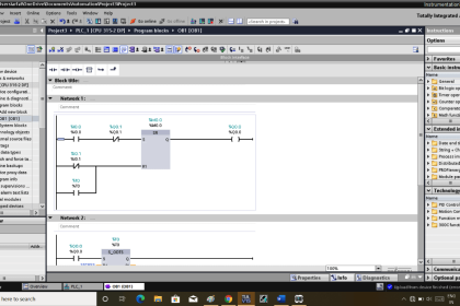
The following computer screenshot shows a typical Ladder Diagram program.

Ladder Diagram

Contacts appear just as they would in an electrical relay logic diagram – as short vertical line segments separated by a horizontal space.

Normally-open contacts are empty within the space between the line segments, while normally-closed contacts have a diagonal line crossing through that space.

Coils are somewhat different, appearing as either circles or pairs of parentheses. Other instructions appear as rectangular boxes.

Each horizontal line is referred to as a rung, just as each horizontal step on a stepladder is called a “rung.”

A common feature among Ladder Diagram program editors, as seen on this screenshot, is the ability to color-highlight those virtual “components” in the virtual “circuit” ready to “conduct” virtual “power.”

In this particular editor, the color used to indicate “conduction” is light blue.

Another form of status indication seen in this PLC program is the values of certain variables in the PLC’s memory, shown in red text.

For example, you can see coil T2 energized at the upper-right corner of the screen (filled with light blue coloring), while coil T3 is not.

Correspondingly, each normally-open T2 contact appears colored, indicating its “closed” status, while each normally-closed T2 contact is uncolored.

By contrast, each normally-open T3 contact is uncolored (since coil T3 is unpowered) while each normally-closed T3 contact is shown colored to indicate its conductive status.

Likewise, the current count values of timers T2 and T3 are shown as 193 and 0, respectively. The output value of the math instruction box happens to be 2400, also shown in red text.

Color-highlighting of Ladder Diagram components only works, of course, when the computer running the program editing software is connected to the PLC and the PLC is in the “run” mode (and the “show status” feature of the editing software is enabled).

Otherwise, the Ladder Diagram is nothing more than black symbols on a white background.

Not only is status highlighting very useful in de-bugging PLC programs, but it also serves an invaluable diagnostic purpose when a technician analyzes a PLC program to check the status of real-world input and output devices connected to the PLC.

This is especially true when the program’s status is viewed remotely over a computer network, allowing maintenance staff to investigate system problems without even being near the PLC!

Credits : by Tony R. Kuphaldt – Creative Commons Attribution 4.0 License

PLC Tutorials :

  • What is Programmable Logic Controller  ?
  • What is Ladder Diagram Programming ?
  • History of Programmable Logic Controllers
  • Mis-conceptions of PLC Ladder Logic
  • Contacts and coils in PLC
  • Digital Input and Output Modules
  • Analog I/O and Network I/O
  • PLC Input/Output Modules
  • Memory Mapping in PLC
  • Analog Input Scaling
  • PLC Example with Switches
  • Counter Instructions
  • Timer Instructions
  • Math instructions
  • Data Instructions
  • Ladder Logic Questions

If you liked this article, then please subscribe to our YouTube Channel for PLC and SCADA video tutorials.

You can also follow us on Facebook and Twitter to receive daily updates.

Don't Miss Our Updates
Be the first to get exclusive content straight to your email.
We promise not to spam you. You can unsubscribe at any time.
Invalid email address
You've successfully subscribed !

Continue Reading

How-to do Security of SCADA Systems?
How to Work with Allen Bradley RsLogix Emulator?
Automatic Railway Crossing Gate Control PLC Program
Learn PLC in Hindi
Boolean Logic to PLC Programming
OPC in Old PLC Systems
Share This Article
Facebook Whatsapp Whatsapp LinkedIn Copy Link
Share
2 Comments
  • javier carrillo sanchez says:
    November 6, 2023 at 1:12 am

    Para mié muy buena información por traer explicaciones muy detallada por lo que me es muy util

    Translated: For me, very good information because it provides very detailed explanations, so it is very useful to me.

    Reply
  • javier carrillo sanchez says:
    November 6, 2023 at 1:18 am

    La programación en escalera es más sencilla de comprender las secuencias ya que siempre tienes que poner las condiciones para una buena secuencia sea semiautomática o automática

    Translated: Ladder programming is easier to understand the sequences since you always have to set the conditions for a good sequence, whether semi-automatic or automatic.

    Reply

Leave a Reply Cancel reply

Your email address will not be published. Required fields are marked *

Stay Connected

128.3kFollowersLike
69.1kFollowersFollow
210kSubscribersSubscribe
38kFollowersFollow

Categories

Explore More

Control Room and Field Instruments Questions and Answers
PLC Program for Blinking Lamp on 5 Seconds Interval
UPS Selection Factors for a Control System
Why Use Normally-Closed Contact for Stop Buttons?
Increment & Decrement Instructions in CX-Programmer (OMRON)
The Purpose of Marshalling Cabinet or Marshalling Panel
Alarm Acknowledge using PLC
Overview of SIEMENS PLC – S7-1500, S7-1200, S7-400, S7-300

Keep Learning

Applications of SCADA

Faceplate in WinCC

Siemens HMI Training – Using UDTs with Faceplates

Siemens S7 300 CPU Status and LED Errors Explanation

Siemens S7 300 CPU Status and LED Errors Explanation

How to troubleshoot the PLC Hardware faults

Hardware Troubleshooting Steps for PLC Automation Systems

Proper Earthing Practices Used for PLC Control Panel

Proper Earthing Practices Used for PLC Control Panel

Conditional Jump instruction

Jump Instruction in Siemens Tia Portal

What is the consumed tag in Studio 5000 software?

Produced Tags and Consumed Tags in Studio 5000

PLC Subroutine

Allen Bradley PLC Subroutines

Learn More

Hook-up Diagram for Pressure Gauge

What is Instrument Hook Up Diagram ?

Critical Factors to Consider for Engineering Students to Ensure a Smooth Path

Critical Factors to Consider for Engineering Students to Ensure a Smooth Path

Quiz on Optical Fiber Cable

Quiz on Optical Fiber Cable, Splice, Connector

Magnetic Float Level Switch Working Animation

Applications of Photo diodes

Applications of Photo diodes

Pneumatic and Hydraulic Projects

200 Pneumatic and Hydraulic Projects List

Image Processing Projects for Engineering Students

Image Processing Projects for Engineering Students

Certification Markings

Flammable Facts

Menu

  • About
  • Privacy Policy
  • Copyright

Quick Links

  • Learn PLC
  • Helping Hand
  • Part Time Job

YouTube Subscribe

Follow US
All rights reserved. Reproduction in whole or in part without written permission is prohibited.
Welcome Back!

Sign in to your account

Username or Email Address
Password

Lost your password?