Inst ToolsInst ToolsInst Tools
  • Ask
  • Courses
  • Videos
  • Q & A
    • Interview
      • Instrumentation
      • Electronics
      • Electrical
      • Practical Questions
    • MCQ
      • Instrumentation MCQ
      • Electrical MCQ
      • Electronics MCQ
      • Control Systems MCQ
      • Analog Electronics MCQ
      • Digital Electronics MCQ
      • Power Electronics MCQ
      • Microprocessor MCQ
      • Multiple Choice Questions
  • EE
    • Electronics
      • Electronics Q & A
      • Electronic Basics
      • Electronic Devices & Circuits
      • Electronics Animation
      • Digital Electronics
    • Electrical
      • Electrical Basics
      • Electrical Q & A
      • Power Electronics
      • Electrical Machines
      • Electrical Animation
      • Power Systems
      • Switchgear & Protection
      • Transmission & Distribution
  • Measure
    • Control Valves
    • Calibration
    • Temperature
    • Pressure
    • Flow
    • Level
    • Analyzers
    • Switches
    • Vibration
    • Solenoid Valve
  • Control
    • PLC Tutorials
    • Control Systems
    • Safety Instrumented System (SIS)
    • Communication
    • Fire & Gas System
  • More
    • Design
    • Tools
    • Animation
    • Basics
    • Formulas
    • Standards
    • TextBooks
    • Common
    • Software
    • Excel Tools
    • Erection & Commissioning
    • Process Fundamentals
    • Videos
    • Books
Search
All rights reserved. Reproduction in whole or in part without written permission is prohibited.
Reading: What is Seal-in Circuit ?
Share
Notification Show More
Font ResizerAa
Inst ToolsInst Tools
Font ResizerAa
  • Courses
  • PLC Tutorials
  • Control Systems
Search
  • Ask
  • Courses
  • Videos
  • Q & A
    • Interview
    • MCQ
  • EE
    • Electronics
    • Electrical
  • Measure
    • Control Valves
    • Calibration
    • Temperature
    • Pressure
    • Flow
    • Level
    • Analyzers
    • Switches
    • Vibration
    • Solenoid Valve
  • Control
    • PLC Tutorials
    • Control Systems
    • Safety Instrumented System (SIS)
    • Communication
    • Fire & Gas System
  • More
    • Design
    • Tools
    • Animation
    • Basics
    • Formulas
    • Standards
    • TextBooks
    • Common
    • Software
    • Excel Tools
    • Erection & Commissioning
    • Process Fundamentals
    • Videos
    • Books
Follow US
All rights reserved. Reproduction in whole or in part without written permission is prohibited.
Inst Tools > Blog > Animation > What is Seal-in Circuit ?

What is Seal-in Circuit ?

Last updated: March 4, 2021 4:33 pm
Editorial Staff
Animation PLC Tutorials
2 Comments
Share
3 Min Read
SHARE

A Seal-in circuit is a method of maintaining current flow after a momentary switch has been pressed and released.

Contents
What is Seal-in Circuit ?PLC Latching AnimationStart Button Not Pressed :Start Button Pressed & Released : 

What is Seal-in Circuit ?

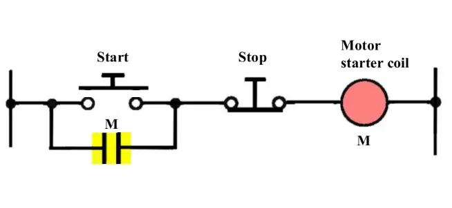
Seal in Circuit working

Fig 1 : Start button not pressed

Note : Consider a Relay is used to control the power supply to a motor. Here we are calling this relay as ” Motor Starter Coil “. This Relay another NO contact is used to seal-in or latch the start signal.

As start push button is a push & Release type i.e. signal will be available for some time say momentarily and then signal will be lost.

so we have to latch this circuit in order to make motor run continuously even after release of start push button.

For this purpose we are using Relay (M) NO contact across Start push button such that it will take care of start signal after start button is released.

The seal-in auxiliary contact (NO Contact) of the starter (M) is connected in parallel with the start button to keep the starter coil (M) energized when the start button released.

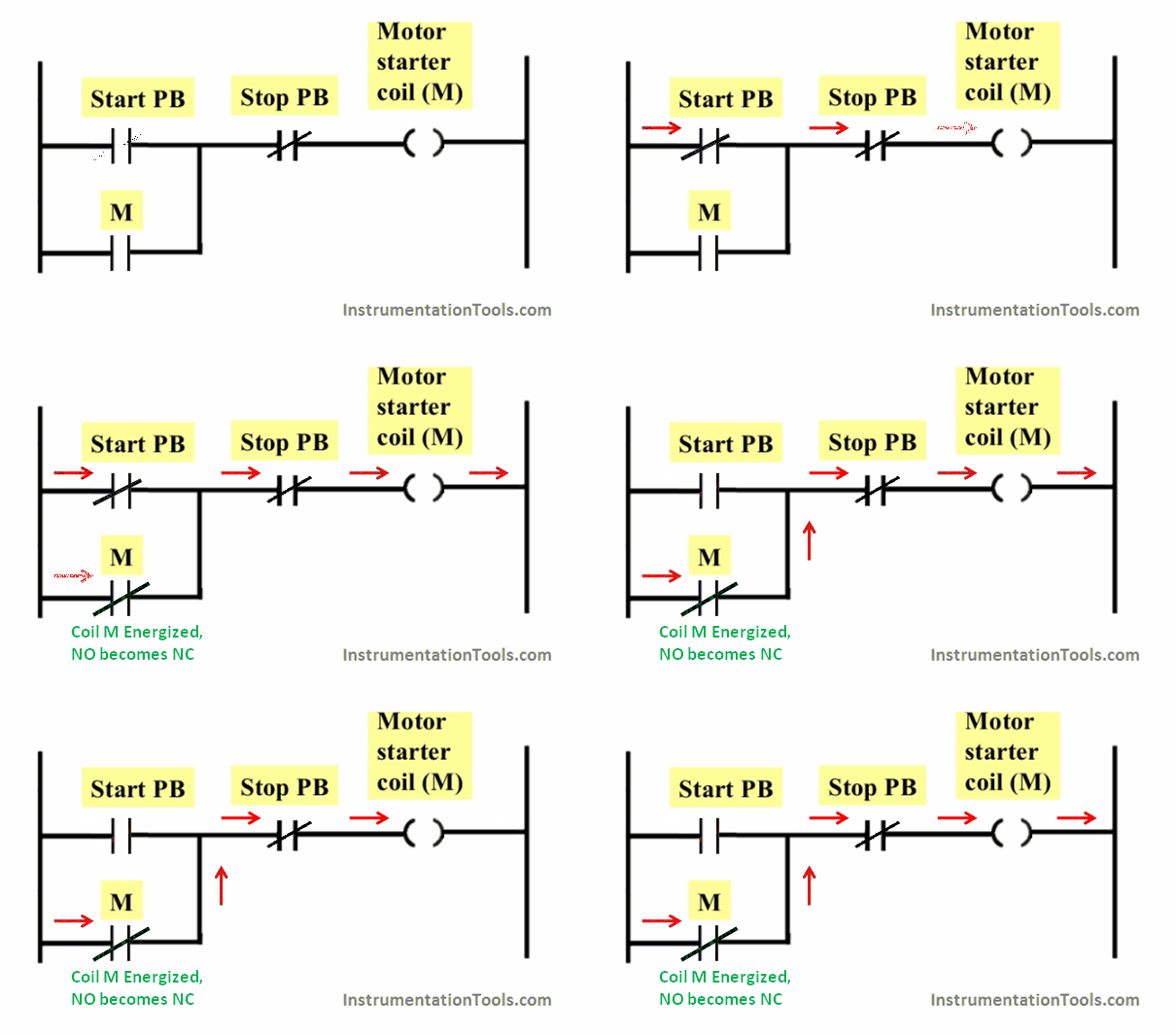
After Start Push button pressed : The Motor starter coil energized and its NO contact becomes NC as shown in below figure.
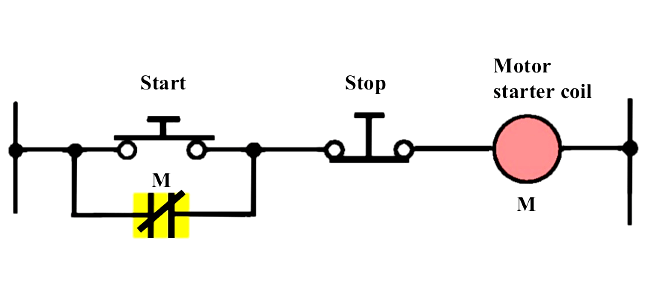
Seal-in Circuit

Fig 2 : Start button pressed

PLC Latching Animation

Start Button Not Pressed :
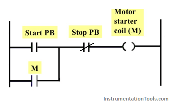
PLC Latching Circuit

Start Button Pressed & Released : 

PLC Latching circuit Animation

During Starting, Start push button will give the signal to energize the coil (M), after that coil NO contact which is connected across

Start Push button will be used to latch the start signal as start push button will be released after pressing ( start button are momentary type ).

Also see : Relay Schematic Animation

If you liked this article, then please subscribe to our YouTube Channel for PLC and SCADA video tutorials.

You can also follow us on Facebook and Twitter to receive daily updates.

Read Next:
  • Latched and Momentary Operation of Motor PLC Program
  • Push button Motor PLC Logic
  • Latches Objective Questions
  • PLC Automatic Control of Two Outputs with one Input
  • Solenoid Operated Valves and Latching Valves
Don't Miss Our Updates
Be the first to get exclusive content straight to your email.
We promise not to spam you. You can unsubscribe at any time.
Invalid email address
You've successfully subscribed !
Site Commissioning Steps for PLC Programmers
How Does Redundant Power Supply Work?
Capacitance Level Transmitter Animation
Factory I/O PLC Automation Training Course (Free)
STAR DELTA Programming using PLC Controller
Share This Article
Facebook Whatsapp Whatsapp LinkedIn Copy Link
Share
2 Comments
  • Trojan says:
    February 17, 2022 at 4:07 pm

    Hi, there is wrong placement of the stop button. The relay will remain latched even when you press the stop button.

    Reply
    • Jeremy Morissette says:
      November 26, 2023 at 11:33 pm

      I had the same thought

      Reply

Leave a Reply Cancel reply

Your email address will not be published. Required fields are marked *

Stay Connected

128.3kFollowersLike
69.1kFollowersFollow
208kSubscribersSubscribe
38kFollowersFollow

Categories

Recent Comments

  • Guifty Shimica on Top Non-PLC Certification Courses for Automation Professionals
  • Guifty Shimica on Top Non-PLC Certification Courses for Automation Professionals
  • MIHARITSOA Aina Sitraka on Top Non-PLC Certification Courses for Automation Professionals
  • Vaishnavi on Free Instrumentation Course for Trainee Engineers

Related Articles

Tags in Functional Block Diagram in Studio 5000

Sheets, Tags, Elements in Functional Block Diagram of Studio 5000

Offline UPS

UPS Working Principle and Types – Offline and Online UPS Systems

Car Wash Program using Functional Block Diagram (PLC)

Car Wash Program using Functional Block Diagram (PLC)

Types of Limit Switches

Types of Limit Switches – Principle, Advantages, Disadvantages

Free Industrial Control System (ICS) Cyber Security Training Course

Free Industrial Control System (ICS) Cyber Security Training Course

PLC Ladder Logic for Lube Oil Pump Motor

PLC Ladder Logic for Lube Oil Pump Motor

PLC Tutorials - Timers and Counters

Difference between Timer and Counter – PLC Basics

PLC to PLC Communication using S7 Connection

PLC to PLC Communication using S7 Connection PUT & GET Instructions

More Articles

PLC PID tuning parameters

Programming and Tuning PID Controller in PLC – Siemens TIA Portal

JMP instruction in PLC Programming

How to use JUMP Instruction in PLC Ladder Logic?

Instrument Air Calculations

Basic Calculations of Instrument Air

Pneumatic and Hydraulic Projects

200 Pneumatic and Hydraulic Projects List

Mass Spectrometer Questions and Answers

Inductively Coupled Plasma Mass Spectrometer

What is a Buchholz Relay

What is a Buchholz Relay? Working Principle

Fire Pump

What is a Fire Pump? – Definition, Principle, Types, Comparison

What is Travel Stop in Control Valve

What is Travel Stop in Control Valve?

Follow US
All rights reserved. Reproduction in whole or in part without written permission is prohibited.
Welcome Back!

Sign in to your account

Username or Email Address
Password

Lost your password?