Triggering (Turn on) Methods of Thyristor:
Triggering:-
The turning on Process of the SCR is known as Triggering. In other words, turning the SCR from Forward-Blocking state to Forward-Conduction state is known as Triggering.The various methods of SCR triggering are discussed here.
The various SCR triggering methods are
- Forward Voltage Triggering
- Thermal or Temperature Triggering
- Radiation or Light triggering
- dv/dt Triggering
- Gate Triggering
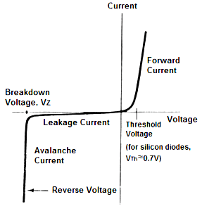
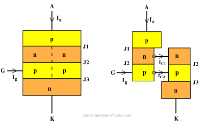
(a) Forward Voltage Triggering:-
- In this mode, an additional forward voltage is applied between anode and cathode.
- When the anode terminal is positive with respect to cathode(VAK) , Junction J1 and J3 is forward biased and junction J2 is reverse biased.
- No current flows due to depletion region in J2 is reverse biased (except leakage current).
- As VAK is further increased, at a voltage VBO (Forward Break Over Voltage) the junction J2 undergoes avalanche breakdown and so a current flows and the device tends to turn ON(even when gate is open)
(b) Thermal (or) Temperature Triggering:-
- The width of depletion layer of SCR decreases with increase in junction temperature.
- Therefore in SCR when VAR is very near its breakdown voltage, the device is triggered by increasing the junction temperature.
- By increasing the junction temperature the reverse biased junction collapses thus the device starts to conduct.
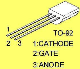
(c) Radiation Triggering (or) Light Triggering:-
- For light triggered SCRs a special terminal niche is made inside the inner P layer instead of gate terminal.
- When light is allowed to strike this terminal, free charge carriers are generated.
- When intensity of light becomes more than a normal value, the thyristor starts conducting.
- This type of SCRs are called as LASCR
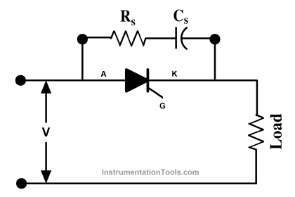
(d) dv/dt Triggering:-
- When the device is forward biased, J1 and J3 are forward biased, J2 is reverse biased.
- Junction J2 behaves as a capacitor, due to the charges existing across the junction.
- If voltage across the device is V, the charge by Q and capacitance by C then,
ic = dQ/dt
Q = CV
ic = d(CV) / dt
= C. dV/dt + V. dC/dt
as dC/dt = 0
ic = C.dV/dt
- Therefore when the rate of change of voltage across the device becomes large, the device may turn ON, even if the voltage across the device is small.
(e) Gate Triggering:-
- This is most widely used SCR triggering method.
- Applying a positive voltage between gate and cathode can Turn ON a forward biased thyristor.
- When a positive voltage is applied at the gate terminal, charge carriers are injected in the inner P-layer, thereby reducing the depletion layer thickness.
- As the applied voltage increases, the carrier injection increases, therefore the voltage at which forward break-over occurs decreases.
- Three types of signals are used for gate triggering.
1. DC gate triggering:-
- A DC voltage of proper polarity is applied between gate and cathode ( Gate terminal is positive with respect to Cathode).
- When applied voltage is sufficient to produce the required gate Current, the device starts conducting.
- One drawback of this scheme is that both power and control circuits are DC and there is no isolation between the two.
- Another disadvantages is that a continuous DC signal has to be applied. So gate power loss is high.
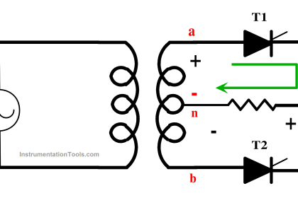
2. AC Gate Triggering:-
- Here AC source is used for gate signals.
- This scheme provides proper isolation between power and control circuit.
- Drawback of this scheme is that a separate transformer is required to step down ac supply.
- There are two methods of AC voltage triggering namely (i) R Triggering (ii) RC triggering
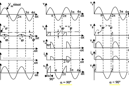
(i) Resistance triggering: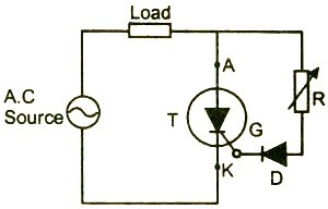
The following circuit shows the resistance triggering.
- In this method, the variable resistance R is used to control the gate current.
- Depending upon the value of R, when the magnitude of the gate current reaches the sufficient value(latching current of the device) the SCR starts to conduct.
- The diode D is called as blocking diode. It prevents the gate cathode junction from getting damaged in the negative half cycle.
- By considering that the gate circuit is purely resistive, the gate current is in phase with the applied voltage.
- By using this method we can achieve maximum firing angle up to 90°.
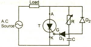
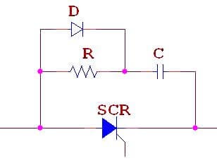
(ii) RC Triggering
The following circuit shows the resistance-capacitance triggering.
- By using this method we can achieve firing angle more than 90°.

- In the positive half cycle, the capacitor is charged through the variable resistance R up to the peak value of the applied voltage.
- The variable resistor R controls the charging time of the capacitor.
- Depends upon the voltage across the capacitor, when sufficient amount of gate current will flow in the circuit, the SCR starts to conduct.
- In the negative half cycle, the capacitor C is charged up to the negative peak value through the diode D2.
- Diode D1 is used to prevent the reverse break down of the gate cathode junction in the negative half cycle.
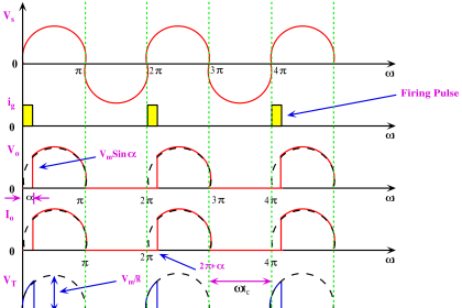
3. Pulse Gate Triggering:-
- In this method the gate drive consists of a single pulse appearing periodically (or) a sequence of high frequency pulses.
- This is known as carrier frequency gating.
- A pulse transformer is used for isolation.
- The main advantage is that there is no need of applying continuous signals, so the gate losses are reduced.
Advantages of pulse train triggering:
- Low gate dissipation at higher gate current.
- Small gate isolating pulse transformer
- Low dissipation in reverse biased condition is possible.So simple trigger circuits are possible in some cases
- When the first trigger pulse fails to trigger the SCR, the following pulses can succeed in latching SCR. This important while
- Triggering inductive circuits and circuits having back emf’s.


Bahut mast kam karta hai re tum bhai log
Mst bhava ????❤️????