A sensor is an input device that provides a usable output in response to the input measurand. A sensor is also commonly called a sensing element, primary sensor, or primary detector. The measurand is the physical parameter to be measured.
An input transducer produces an electrical output that is representative of the input measurand. Its output is conditioned and ready for use by the receiving electronics like PLC or DCS.
The receiving electronics can be an indicator, controller, computer, PLC, DCS etc. The term “transmitter,” as commonly used with industrial process control instrumentation, has a more narrow definition than those of a sensor or transducer:
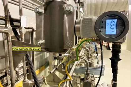
4-20 mA Transmitter
A transmitter is a transducer that responds to a measured variable by means of a sensing element and converts it to a standardized transmission signal (like 4-20mA) that is a function only of the measured variable.
Transmitters can have any of several electrical connection schemes. The most common and easiest to use is the two-wire, loop-powered configuration.
This is generally the basic configuration for industrial process control systems when digital communication is not required.
As shown in Below Figure, only two wires are used to accommodate both power to the transmitter and output signal from the transmitter.
To facilitate a closed-loop control system, information from the process must be obtained before a controller can determine what action may be required by a control element. Some popular names for the sensing devices that provide the information are sensors, transducers, and/or transmitters.
The standard loop current is usually 4 to 20 mA. Important calibration parameters with a current loop are Zero, full scale, and span.
With the 4- to 20mA range, the loop current is normally 4 mA when the measurand or Process Variable is at zero, and 20 mA when the measurand or Process Variable is at full scale.
The difference between Zero and full scale, 16 mA, is called the span. Thus, the span corresponds to the indicated range of the measurand or Process Variable.
When considering a flow transmitter, for example, the range of the measurand or Process Variable is 0.0 to 100.0 m3/hr, corresponding to a 4- to 20-mA loop current (output span is then 16 mA); the output scaling factor is 0.16 mA/(m3/hr) (which is 100 m3/hr 16 mA).
4-20mA Transmitter Works
Assumptions : Standard +24V DC with 20mA
In General PLC / DCS Analog Input card channel supplies more than 20mA current to power the loop.
Case 1 : Process Variable @ 0%
The PLC / DCS Analog Input card transmits a standard +24 V DC, 20 mA signal to Power the Transmitter.
A one pair cable is used to power the transmitter and the same cable is used to receive the data in the 4-20mA current range.
Transmitter receives +24V DC, more than 20mA signal in the loop. A minimum +5V DC, 20mA signal is required to proper functioning of transmitter. In Practical there will be a voltage drop in the loop.
Transmitter have an inbuilt voltage regulator function which is used to regulate the loop current. The Transmitter will be configured with LRV, URV and other details of Process variable. The loop current will be varied / changed by the transmitter as per the measured Process variable.
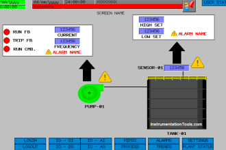
The 4-20mA current will be converted into standard 1 – 5 V DC using a precision 250 ohms resistor. The Analog to Digital converter will be used to convert the voltage into digital signal which is used to indicate the Process Variable value in the DCS / PLC HMI.
Example:
A Flow Transmitter with a range of 0 to 100 m3/hr. Transmitter indicates 0 m3/hr as there is no flow in the line. DCS / PLC powers the transmitter with +24V DC, 20mA.
As Process Variable is 0 m3/hr, the transmitter regulates the loop current to 4mA and its equivalent voltage is 1 V DC which is measured by A/D Converter which indicates 0% of Process Variable.

Note: The loop current will be same either at starting or end or any point in the loop. For easy understanding only, both 20mA & 4 mA signals are shown in the animation.
In Practical, When we measure the current at any point in the loop, the transmitter output current will be found i.e. 4mA as per above figure, so just assume DCS/PLC system powers the loop with +24V DC, 20mA (generally systems supplies more than 20mA) while transmitter regulates the loop current within 4mA to 20mA as per its configuration & real time process variable value.
If you want to measure the PLC/DCS loop power i.e. 20mA (as per above figure) signal then disconnect the transmitter from the loop & Connect the multimeter in series with DCS/PLC to measure the loop current. And the one pair cable is a twisted pair cable.
Case 2 : Process Variable @ 50%
Same Principle applies. The Transmitter adjust the loop current as per the Process Variable.
The only difference is the transmitter sensing element changes its output as process variable varied from 0% to 50%. The transmitter regulates the loop current as per the sensing element.
Example:
Process variable indicates 50 m3/hr. Transmitter regulates output to 12mA in the loop as per the configured range and measured process variable and its equivalent voltage is 3 V DC which is measured by A/D Converter which indicates 50% of Process Variable.

Case 3 : Process Variable @ 100%
Same Principle applies. The Transmitter adjust the loop current as per the Process Variable.
The only difference is the transmitter sensing element changes its output as process variable varied from 50% to 100%. The transmitter regulates the loop current as per the sensing element.
Example:
Process variable indicates 100 m3/hr. Transmitter regulates outputs to 20mA in the loop as per the configured range and measured process variable and its equivalent voltage is 5 V DC which is measured by A/D Converter which indicates 100% of Process Variable.

Video Lesson
Process Variable
Although almost any type of transducer can be configured as a transmitter, the most common types for industrial process control comprise measurands or Process Variables like temperature, pressure, flow, level etc.
Transmitters for measuring other parameters will have the same possibilities for connection and communication methods, with the main differences being in the sensing element design of transmitter and electronic equipment will be same with slightly software modification.
Two Wire Loops
The main advantage of a two-wire loop is that it minimizes the number of wires needed to run both power and signal. The use of a current loop to send the signal also has the advantages of reduced sensitivity to electrical noise and to loading effects.
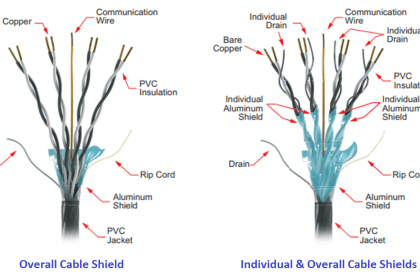
The electrical noise is reduced because the two wires are run as a twisted pair, ensuring that each of the two wires receives the same vector of energy from noise sources, such as electro- magnetic fields due to a changing current in a nearby conductor or electric motor.
Since the receiving electronics connected to the transmitter is designed to ignore common-mode signals, the resulting common-mode electrical noise is ignored.
The sensitivity to loading effects is reduced because the current in the twisted pair is not affected by the added resistance of long cable runs.
A long cable or other series resistance will cause a greater voltage drop but does not affect the current level as long as enough voltage compliance is available in the circuit to supply the signal current.
Also Read : How PLC controls a Motor ?
The circuit compliance to handle a given voltage drop from additional loop devices depends on the transmitter output circuit and on the power supply voltage.
The typical power supply for industrial transmitters is +24 VDC. If 6 volts, for example, are needed to power the transmitter and its output circuit, then 18 volts of compliance remain to allow for wire resistance, load resistance, voltage drops across intrinsic safety (IS) barriers and remote displays, etc.
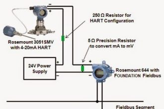
Where the current loop signal is connected to the main receiving equipment (PLC/DCS) or data acquisition system, a precision load resistor of 250 ohms is normally connected.
This converts the 4 to 20 mA current signal into a 1 to 5 volt signal, since it is standard practice to configure the analog-to-digital converter of the receiving equipment (PLC/DCS) as a voltage-sensing input.
Three and Four Wire Loops
In contrast to the two-wire current-loop configuration, some current-loop devices require a three or four wire connections. These are not loop powered and therefore have a separate means for providing power by adding one or two more wires.
In a four-wire configuration, the current-loop wires can be a twisted pair, and the power supply wires a separate twisted pair. This preserves the ability to reject electrical and magnetic common-mode interference. This is not so effective in a three-wire configuration due to the common connection for the return current path.
Typically, though, when an instrumentation engineer specifies a current-loop transmitter for industrial process control, it is assumed that a two-wire, loop-powered 4 to 20 mA device is intended.
Other data signals may also be impressed upon the same wire pair, or alternatively, various digital communication techniques can be used instead of a current loop, if required.
If you liked this article, then please subscribe to our YouTube Channel for Instrumentation, PLC, and SCADA video tutorials.
You can also follow us on Facebook and Twitter to receive daily updates.
Read Next:
- RTD Calibration
- Final Control Elements
- Basics of Loop Checks
- Instrumentation & Control
- DP Level Transmitter Errors


very good info
Excellent Article. No one is providing information but you Mr.Bharadwaj – you are great. Thank you for everything.
Thanks a lot…great information…
thanks sir
Very useful thanks
I need print options
Thanks sir
Please let me know the print options to save this valuable information
I am working on it. As soon as possible the options will be configured.
Thank you very much.
Thank you so much sir
Excellent information.
Hi Bro,
Hru? i’ve seen some year before but i’m not concentration of this. Really i’m saying it is good work and good information to every one. pl continue the job. God support to u and God bless u.
thanking u,
with regards,
Paranthaman.T
sir, thanks for your contribution for instrument personnels. please continue your work for others
Thanku sir…….valuable data
Nunca vi um site com tanta boa informação.
Muito obrigado.
Translated from portuguese to english:
I have never seen a site with so much good information.
Thank you very much.
Thank you!!
valuable information
sir who introduced this term 4-20 mA . why it can be like 5-50 mA or some other else. Any history behind?
4-20mA is a common 24V instrumentation signal standard which equates with a 1-5V DC input signal when a 250ohm resistor is connected in parallel (shunt) configuration.
Using ohms law IxR=V
eg…..4mA(0.004)X250=1V
……..20mA(0.020)X250=5V
The 250 ohm resistor is in series with the 4-20mA loop. Current loops are series circuits only!
The resistor is in parallel with the high impedance VOLTAGE input to the signal input to the PLC/DCS card or data acquisition card.
hi.. sir very thankful to you, shared very good information with us,please continue
Dear Sir
Really very good article and information you have explained for process automation.
Also I would like to mention that the 4-20mA loop only draws what the transmitter output is. All current that leaves the power supply (sourced) has to return to the power supply. The transmitter will not draw more than the alarm amount above 20mA (e.g.: 20.5 or 22.5 mA) and it will only deliver to the input card and back to power supply negative what it draws.
What leaves the power supply, returns to the power supply!
Very Important! Most transmitters require 10.5 to 13.8 volts to operate after calculating the voltage drop in the circuit. e.g.: 1.2 volts in wire VD + 10.5 volts for transmitter to operate = 11.7 volts minimum supply voltage.
Thank you Mr.Brown Lewis for sharing your knowledge with us. Have a Good Day. Thanks.
thank u sir, introduction for instrumentation tutorials.
Very good information about transmitter and it’s operation
Very useful post
You provided valuable information for every instrumentation students and employees also keep doing your research…. Thank you….
Thank you for your good thinking and sharing.
Thank you so much…
dear, sir thanx
transmitter concept easy to understand by this animated block diagram…thank for shairing such good information
As a mechanical Engineer for me it was very knowledgable and simple to understand.
thank you very much
why 4-20 current get drop in loop powered circuit?
you provided valueable knowledge Thank you so much
Excellent illustration. Thanks for sharing
Easy to understand, great piece of work
dear Mr. S Bharadwaj.
pls refer … we are trying to make people independent business owner in instrumentation , calibration, validation and some other division. We fund 100% for them .
i can see you are doing tremendous work for everyone. If you support us, it might help to many serious people to become business owner very soon.
as if people become technically strong, they can deliver better result.
i will be happy to have word with you,
i will lookforward to have your guidance .
Hi, I am not interested in any type of Sales/business. Thanks
thankx……….sir
fantastic explanation.
simple and great.
even non instrument people too will understand quickly.
Thank you sir for such a wonderful presentation
thanx for you wonderful presenation sir,,,
Very good simulation/training.
Excellent illustration. Thanks
Sir please give brief explanation of 4-20ma measurement through multimeter
Honorable Sir ,
Please give in video with explanation of 4-20ma measurement through multi meter.
sir why we are saying output of transmitter as 4-20 ma (current).why aren’t we giving more importantss to current than voltage,since for every electric devices we say output in terms of voltage and is mentioned only secondary.
A very useful article with simple explanation to understand the working principle of the sensors providing the 4mA to 20mA output. Thank you for this article.
If the flow transmitter is very far , let’s say 1km away from the PLC, whether we will be using the same 4-20 mA wire? ,It may cause loss
Hahaha! Yeah!!