This article discusses the control of a 3-floor automated parking system using Omron PLC ladder logic. The system is designed to manage the car parking process by displaying available parking slots on each floor. Using indicator lights, the system enables drivers to identify floors with vacant parking spaces and select an available area. It tracks vehicle entries and exits to maintain accurate parking availability data. When the parking facility is full, the system notifies drivers and prevents further entries.
Program Objective
The Car Parking Process in an Automated Parking System:
- Vehicle Entry Detection
- The system detects a car entering the parking area.
- The system checks the availability of empty parking slots on each floor.
- Parking Slot Information per Floor
- Each floor has 10 parking slots, each with its own exit gate.
- There are vehicle exit detection sensors on each floor to monitor cars leaving the parking area.
- Parking Data Update
- If a sensor detects a car exiting, the system automatically reduces the number of parked vehicles recorded on that floor.
- Parking Location Assignment
- If there is more than one floor with available slots, the driver can choose their preferred parking floor.
- The system records the number of incoming cars based on the driver’s selected floor.
- Parking Gate Opening
- After the driver selects a floor, the parking gate opens for 10 seconds to allow entry.
- Full Parking Indicator
- If no empty slots are available on any floor, the system will turn on the “FULL” indicator light, signaling that the parking area is at full capacity.
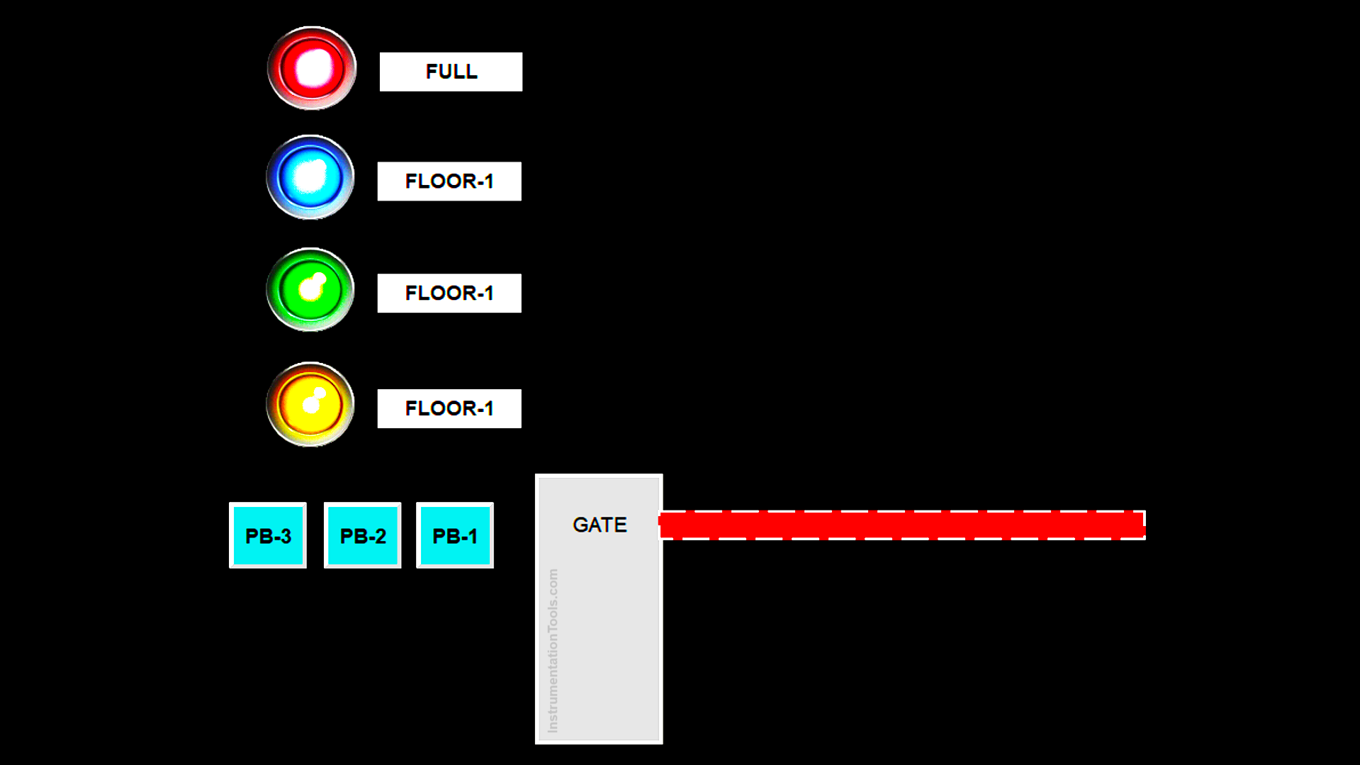
3-Floor Parking System
IO Mapping
| S.No. | Comment | Input (I) | Output (Q) | Memory Bit | Memory Word | Timer |
|---|---|---|---|---|---|---|
| 1 | START | 0.00 | ||||
| 2 | STOP | 0.01 | ||||
| 3 | SENS_CAR | 0.02 | ||||
| 4 | PB_FLOOR1 | 0.03 | ||||
| 5 | PB_FLOOR2 | 0.04 | ||||
| 6 | PB_FLOOR3 | 0.05 | ||||
| 7 | SENS_OUT1 | 0.06 | ||||
| 8 | SENS_OUT2 | 0.07 | ||||
| 9 | SENS_OUT3 | 1.00 | ||||
| 10 | LAMP_FLOOR1 | 100.00 | ||||
| 11 | LAMP_FLOOR2 | 100.01 | ||||
| 12 | LAMP_FLOOR3 | 100.02 | ||||
| 13 | GATE_OPEN | 100.03 | ||||
| 14 | LAMP_FULL | 100.04 | ||||
| 15 | COUNT_FLOOR1 | D0 | ||||
| 16 | COUNT_FLOOR2 | D1 | ||||
| 17 | COUNT_FLOOR3 | D2 | ||||
| 18 | TIMER_GATE | T0000 | ||||
| 19 | SYSTEM_ON | W0.00 | ||||
| 20 | CAR_DETECT | W0.01 |
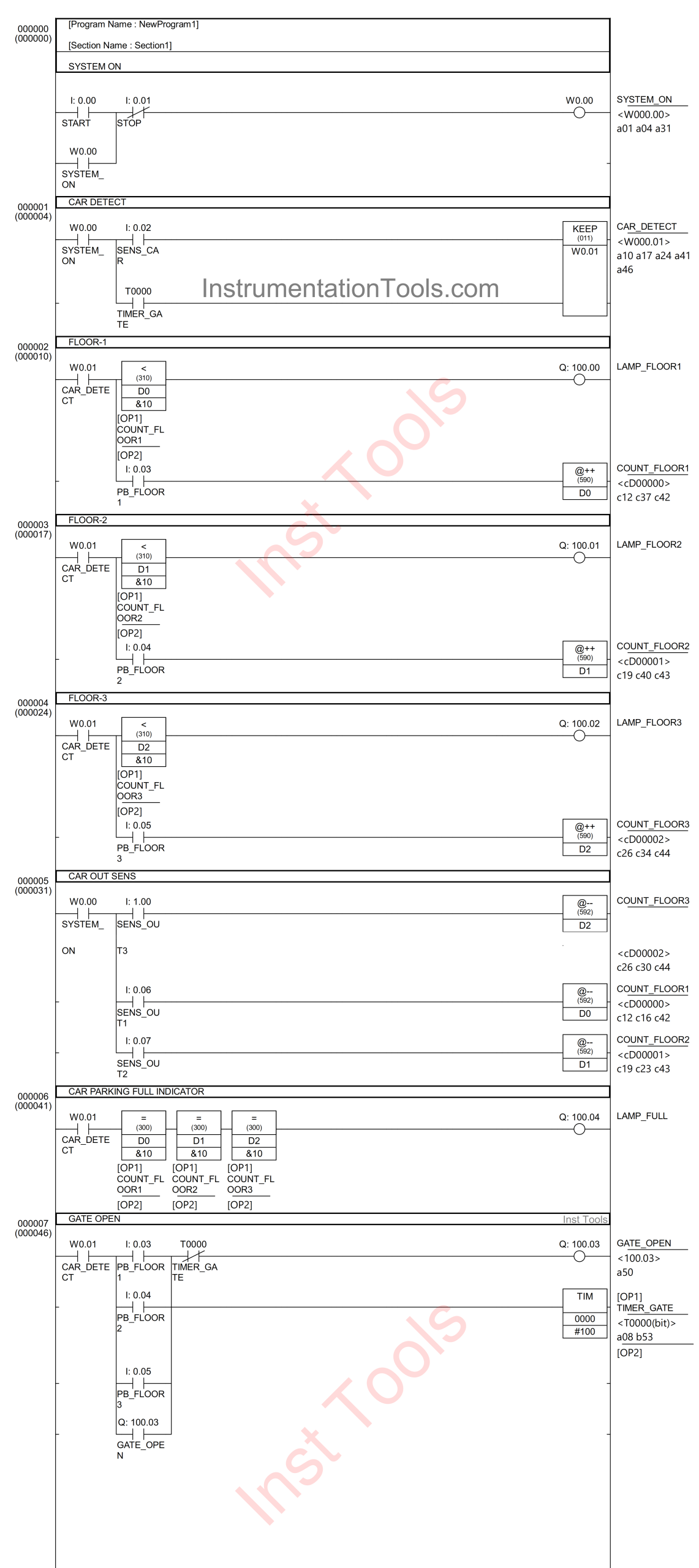
Omron PLC Ladder Logic
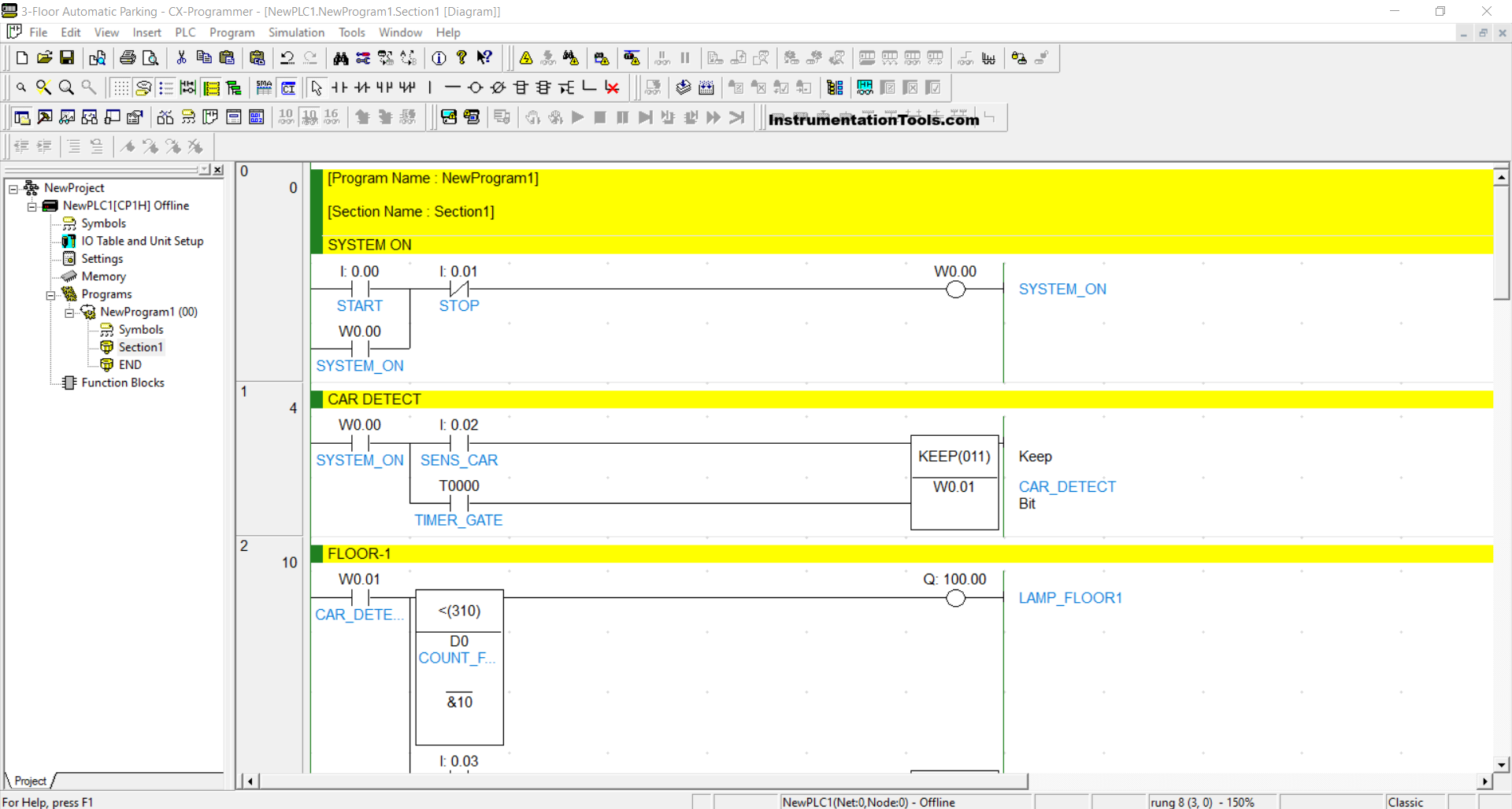
RUNG 0 (SYSTEM ON)
In this Rung, if the START (0.00) button is pressed, the memory bit SYSTEM_ON (W0.00) will be in a HIGH state. Because it uses Latching, the memory bit SYSTEM_ON (W0.00) will remain in a HIGH state even though the PB_START (0.00) button has been released.
The memory bit SYSTEM_ON (W0.00) will return to a LOW state if the STOP (0.01) button is pressed.
RUNG 1 (CAR DETECT)
In this Rung, when the NO contact of the memory bit SYSTEM_ON (W0.00) and the SENS_CAR (0.02) sensor are in a HIGH state, the memory bit CAR_DETECT (W0.01) will be in a HIGH state. Because it uses the KEEP(011) instruction, the memory bit CAR_DETECT (W0.01) will remain in the HIGH state even though the NO contact of the SENS_CAR (0.02) sensor has been in the LOW state. The memory bit CAR_DETECT (W0.01) will be in the LOW state if the NO contact of the TIMER_GATE (T0000) timer has been in the HIGH state.
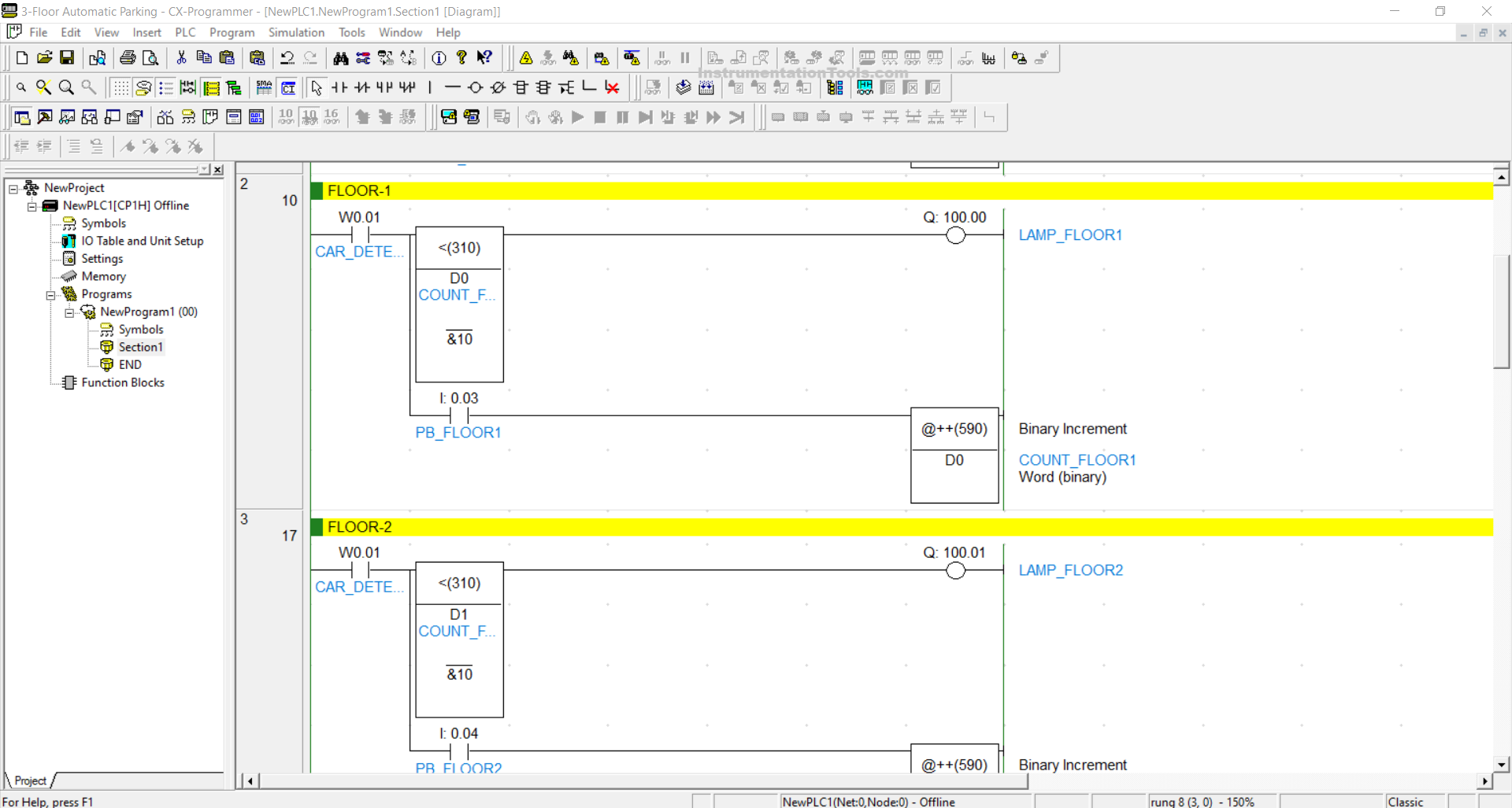
RUNG 2 (FLOOR-1)
In this Rung, when the NO contact of the memory bit CAR_DETECT (W0.01) and the memory word COUNT_FLOOR1 (D0) is Less Than “10”, the LAMP_FLOOR1 (100.00) output will be ON.
When the PB_FLOOR1 (0.03) button has been pressed, the value of the memory word COUNT_FLOOR1 (D0) will increase (+1) because it uses the Binary Increment / @++(590) instruction.
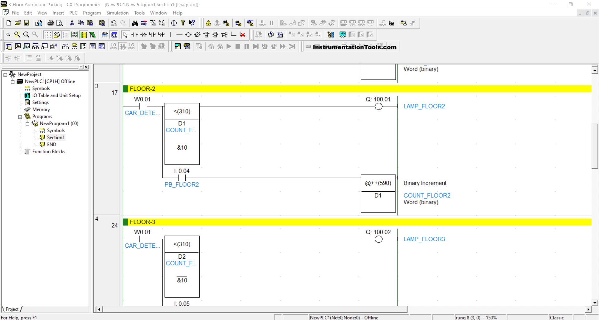
RUNG 3 (FLOOR-2)
In this Rung, when the NO contact of the memory bit CAR_DETECT (W0.01) and the memory word COUNT_FLOOR2 (D1) is Less Than “10”, the LAMP_FLOOR2 (100.01) output will be ON.
When the PB_FLOOR2 (0.04) button has been pressed, the value of the memory word COUNT_FLOOR2 (D1) will increase (+1) because it uses the Binary Increment / @++(590) instruction.
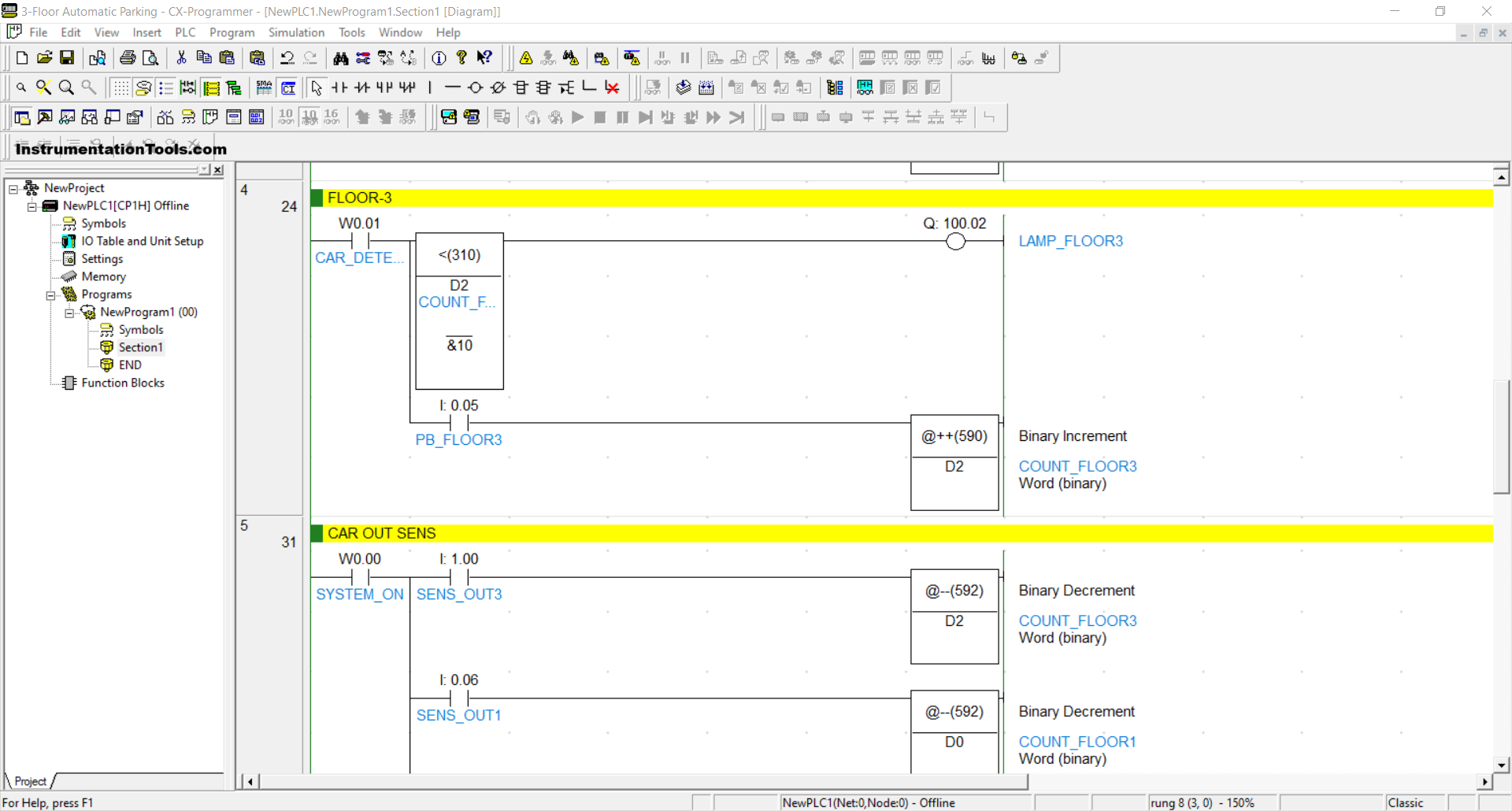
RUNG 4 (FLOOR-3)
In this Rung, when the NO contact of the memory bit CAR_DETECT (W0.01) and the memory word COUNT_FLOOR3 (D2) is Less Than “10”, the LAMP_FLOOR3(100.02) output will be ON.
When the PB_FLOOR3 (0.05) button has been pressed, the value of the memory word COUNT_FLOOR3 (D2) will increase (+1) because it uses the Binary Increment / @++(590) instruction.
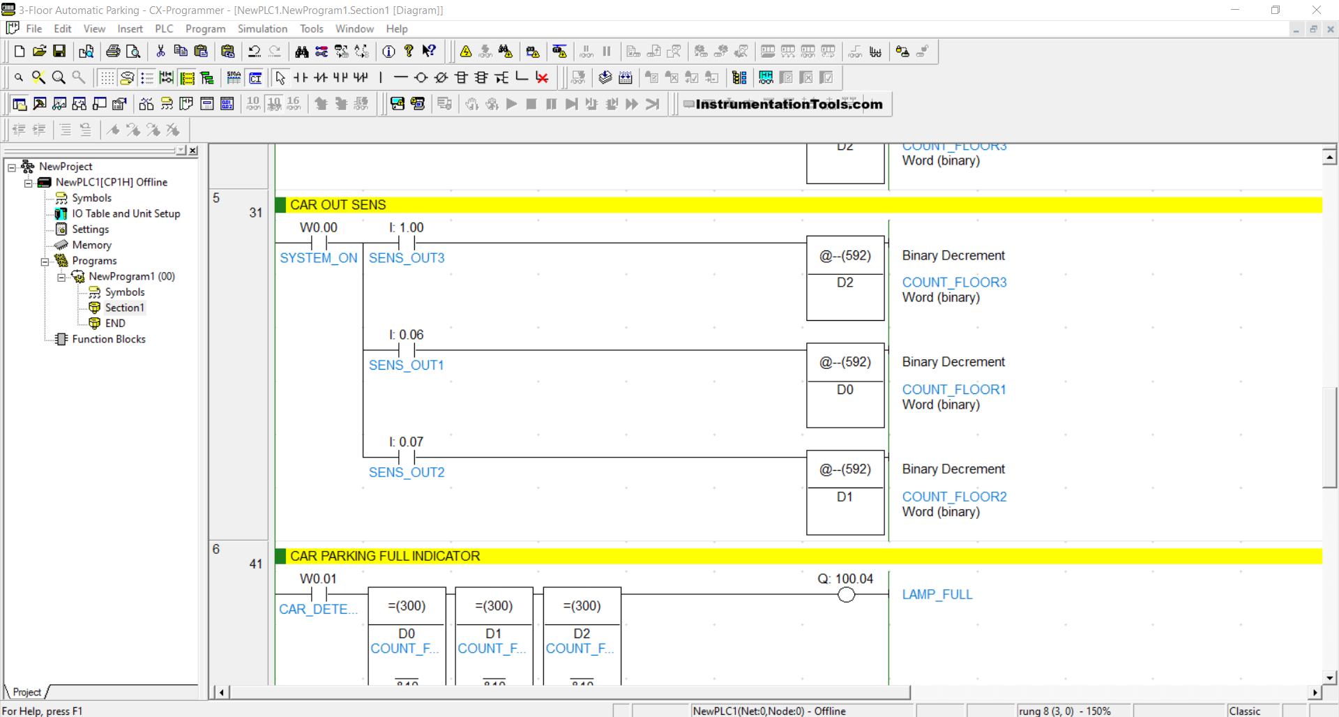
RUNG 5 (CAR OUT SENS)
In this Rung, when the NO contact of the memory bit SYSTEM_ON (W0.00) and the SENS_OUT1 (0.06) sensor are in the HIGH state, the value in the memory word COUNT_FLOOR1 (D0) will decrease (-1) because it uses the Binary Decrement/@++(592) instruction.
When the SENS_OUT2 (0.07) sensor is in the HIGH state, the value in the memory word COUNT_FLOOR2 (D1) will decrease (-1) because it uses the Binary Decrement/@++(592) instruction.
And, when the SENS_OUT3(1.00) sensor is in the HIGH state, the value in the memory word COUNT_FLOOR3 (D2) will decrease (-1) because it uses the Binary Decrement/@++(592) instruction.
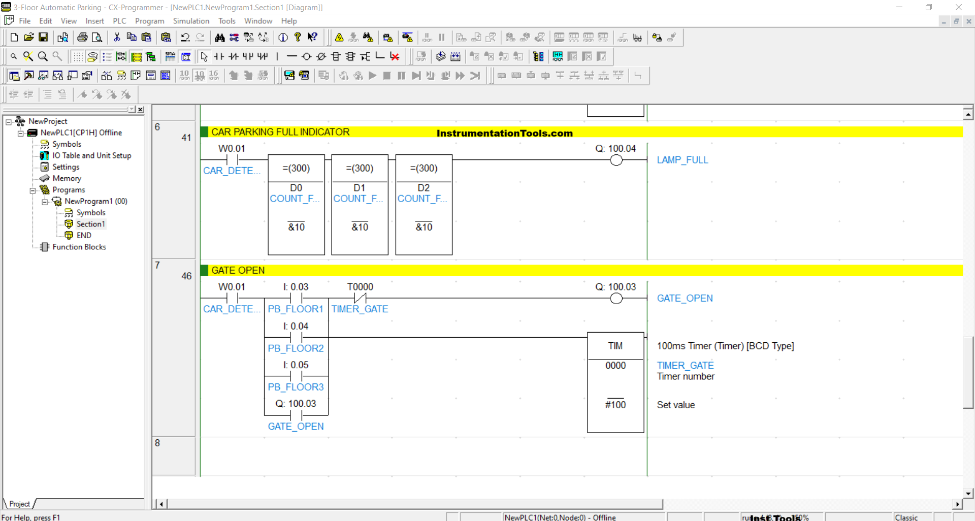
RUNG 6 (CAR PARKING FULL INDICATOR)
The output LAMP_FULL (100.04) will be ON if the NO contact of the memory bit CAR_DETECT (W0.01) is in the HIGH state and the value of the memory words COUNT_FLOOR1 (D0), COUNT_FLOOR2 (D1), and COUNT_FLOOR3 (D2) is Equal To “10”.
RUNG 7 (GATE OPEN)
When the NO contact of the memory bit CAR_DETECT (W0.01) is in the HIG state and any of the buttons PB_FLOOR1 (0.03), PB_FLOOR2 (0.04), or PB_FLOOR3 (0.05) is pressed, the output GATE_OPEN (100.03) will be ON and the TIMER_GATE (T0000) timer will start counting up to 10 seconds.
The GATE_OPEN (100.03) will remain ON even if any of the buttons PB_FLOOR1 (0.03), PB_FLOOR2 (0.04), PB_FLOOR3 (0.05) have been released. When the TIMER_GATE (T0000) timer has finished counting, the GATE_OPEN (100.03) output will become OFF due to the Interlock.
Read Next:
- Car Parking System with Calculations in PLC Programming
- PLC Program to Mix 4 Materials with Time and Weight Control
- Single-acting Pneumatic Cylinder Operation with Limit Switch
- Automatically Close Pop-up in FactoryTalk View Studio
- Simulation of Studio 5000 and FactoryTalk View Studio