Inst ToolsInst ToolsInst Tools
  • Ask
  • Courses
  • Videos
  • Q & A
    • Interview
      • Instrumentation
      • Electronics
      • Electrical
      • Practical Questions
    • MCQ
      • Instrumentation MCQ
      • Electrical MCQ
      • Electronics MCQ
      • Control Systems MCQ
      • Analog Electronics MCQ
      • Digital Electronics MCQ
      • Power Electronics MCQ
      • Microprocessor MCQ
      • Multiple Choice Questions
  • EE
    • Electronics
      • Electronics Q & A
      • Electronic Basics
      • Electronic Devices & Circuits
      • Electronics Animation
      • Digital Electronics
    • Electrical
      • Electrical Basics
      • Electrical Q & A
      • Power Electronics
      • Electrical Machines
      • Electrical Animation
      • Power Systems
      • Switchgear & Protection
      • Transmission & Distribution
  • Measure
    • Control Valves
    • Calibration
    • Temperature
    • Pressure
    • Flow
    • Level
    • Analyzers
    • Switches
    • Vibration
    • Solenoid Valve
  • Control
    • PLC Tutorials
    • Control Systems
    • Safety Instrumented System (SIS)
    • Communication
    • Fire & Gas System
  • More
    • Design
    • Tools
    • Animation
    • Basics
    • Formulas
    • Standards
    • TextBooks
    • Common
    • Software
    • Excel Tools
    • Erection & Commissioning
    • Process Fundamentals
    • Videos
    • Books
Search
All rights reserved. Reproduction in whole or in part without written permission is prohibited.
Reading: Sequential PLC Programming for the Pneumatic Valves
Share
Notification Show More
Font ResizerAa
Inst ToolsInst Tools
Font ResizerAa
  • Courses
  • PLC Tutorials
  • Control Systems
Search
  • Ask
  • Courses
  • Videos
  • Q & A
    • Interview
    • MCQ
  • EE
    • Electronics
    • Electrical
  • Measure
    • Control Valves
    • Calibration
    • Temperature
    • Pressure
    • Flow
    • Level
    • Analyzers
    • Switches
    • Vibration
    • Solenoid Valve
  • Control
    • PLC Tutorials
    • Control Systems
    • Safety Instrumented System (SIS)
    • Communication
    • Fire & Gas System
  • More
    • Design
    • Tools
    • Animation
    • Basics
    • Formulas
    • Standards
    • TextBooks
    • Common
    • Software
    • Excel Tools
    • Erection & Commissioning
    • Process Fundamentals
    • Videos
    • Books
Follow US
All rights reserved. Reproduction in whole or in part without written permission is prohibited.
Inst Tools > Blog > PLC Tutorials > Sequential PLC Programming for the Pneumatic Valves

Sequential PLC Programming for the Pneumatic Valves

Write a ladder logic for sequential PLC programming for the pneumatic valves to operate cylinders in sequential mode.

Last updated: May 23, 2023 2:17 pm
Editorial Staff
PLC Tutorials
No Comments
Share
2 Min Read
SHARE

This is a PLC program for pneumatic valve operation in sequence mode.

Contents
Sequential PLC Programming for the Pneumatic ValvesList of inputs/outputsLadder Diagram for the Sequential Operation of Cylinders

Sequential PLC Programming for the Pneumatic Valves

Write a ladder logic for sequential PLC programming for the pneumatic valves to operate cylinders in sequential mode.

Pneumatic valve operation in sequence mode

Solution:

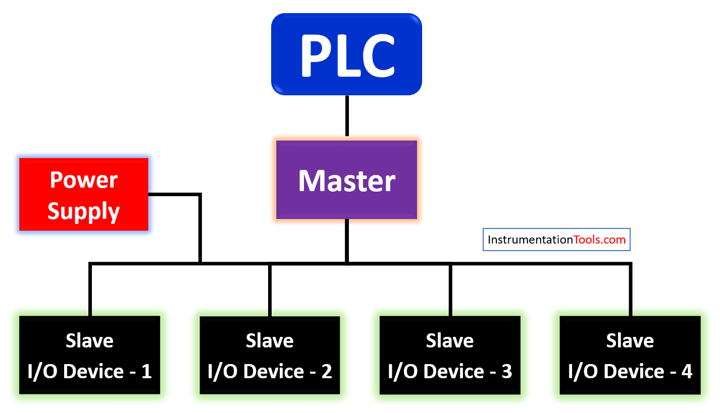
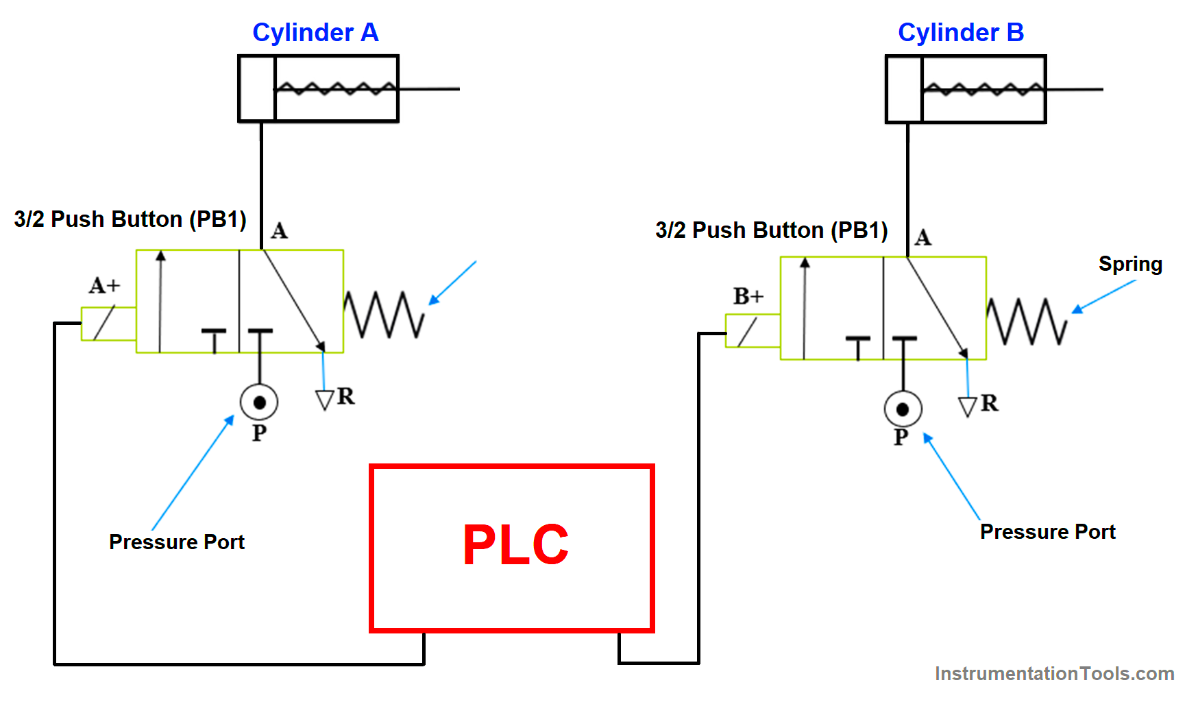
Here in this system, there are two cylinders and two push buttons that are connected to the PLC.

 The push buttons are connected to the PLC inputs and the cylinders are connected to the Outputs of the PLC.

There are the following condition for the system to work which are as follows: –

When START PB is pushed, cylinder A should start, and Cylinder B should start after 5 seconds of Cylinder A.

When STOP PB is pushed, both cylinders A & B are to be stopped.

Now to meet the following conditions, we must use a timer which delays the operation of cylinder B.

List of inputs/outputs

Inputs:

  1.  X1 -START PB
  2.  X2 -STOP PB

Outputs:

  1.  Y0 -Cylinder A
  2.  Y1 -Cylinder B

Ladder Diagram for the Sequential Operation of Cylinders

Sequential PLC Programming for the Pneumatic Valves

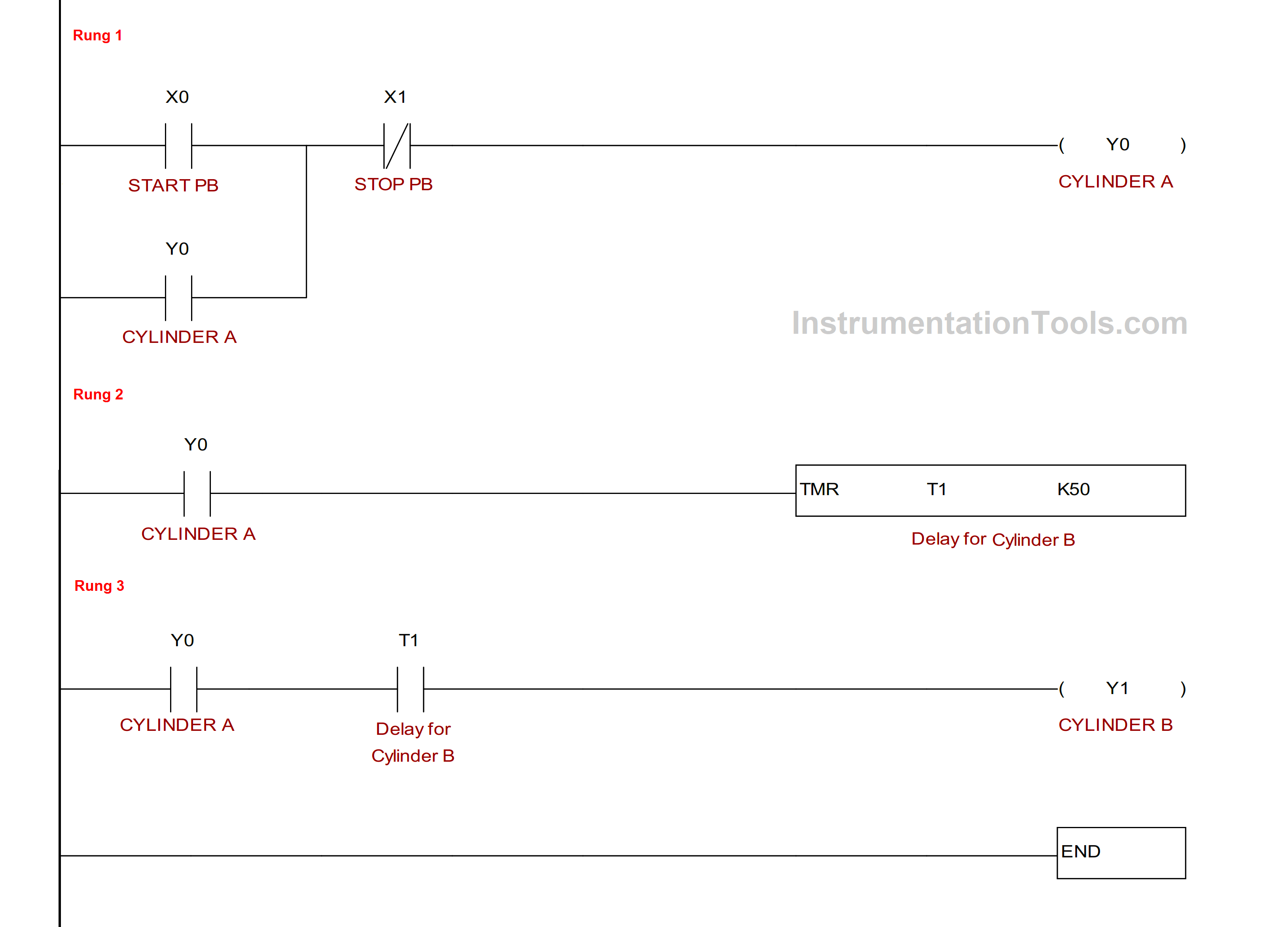
Program Explanation:

In rung 1, we used STRAT PB (X1) to start Cylinder A (Y0). Here we used NC contact of STOP PB (X2) to stop cylinder A (Y0). In parallel with X1 contact, we used NO contact of Y0 to latch the output.

In rung 2, we used Timer T0 to count the delay for cylinder B (Y1).

In rung 3, we used NO contact of T0 so once time delay over the Cylinder B (Y1) will ON.

If you liked this article, then please subscribe to our YouTube Channel for Instrumentation, Electrical, PLC, and SCADA video tutorials.

You can also follow us on Facebook and Twitter to receive daily updates.

Read Next:

  • PLC Restrict Data Interfaces
  • Use PLC Flags as Integrity Checks
  • Offline and Online UPS Systems
  • Diagnostic Buffer for SIEMENS PLC
  • S7-1200 Hardware Configuration
Don't Miss Our Updates
Be the first to get exclusive content straight to your email.
We promise not to spam you. You can unsubscribe at any time.
Invalid email address
You've successfully subscribed !
Rockwell PLCs for Large Scale Applications
Learn about PLC, DCS, RTU, SCADA, and PAC
PLC Timer Programming Examples – TON, TOF, TP and TONR
Power Supply Sizing for Industrial Automation Systems
Types of Industrial Control Systems
Share This Article
Facebook Whatsapp Whatsapp LinkedIn Copy Link
Share
Leave a Comment

Leave a Reply Cancel reply

Your email address will not be published. Required fields are marked *

Stay Connected

128.3kFollowersLike
69.1kFollowersFollow
208kSubscribersSubscribe
38kFollowersFollow

Categories

Recent Comments

  • Guifty Shimica on Top Non-PLC Certification Courses for Automation Professionals
  • Guifty Shimica on Top Non-PLC Certification Courses for Automation Professionals
  • MIHARITSOA Aina Sitraka on Top Non-PLC Certification Courses for Automation Professionals
  • Vaishnavi on Free Instrumentation Course for Trainee Engineers

Related Articles

What is meant by the Batching Process

Batch Simulator PLC Example Program using LogixPro Simulator

Difference Between Wifi and Industrial Wireless

Difference Between Wifi and Industrial Wireless

PLC Programming Example with Pushbutton and Motor

PLC Programming Example with Pushbutton and Motor

Transistor Output Wiring

PLC Output Types

Best PLC for Your Project

Finding the Best PLC for Your Project – Tips and Tricks

Contextual HMI

What is Contextual HMI? – HMI Screens on a Mobile or Tablet

Actuator Sensor Interface (ASi) Protocol in PLC

Actuator Sensor Interface (ASi) Protocol in PLC

Types of Limit Switches

Types of Limit Switches – Principle, Advantages, Disadvantages

More Articles

Industrial Instrumentation Questions & Answers

Industrial Instrumentation Questions & Answers

P&ID arrangement for Pressure Safety Valves

P&ID Guidelines for Pressure Safety Valves

Ladder Logic Questions and Answers

Ladder Logic MCQ Questions and Answers

Infrared Hydrocarbon Gas Detector Calibration Procedure

Infrared Hydrocarbon Gas Detector Calibration Procedure

AI AO DI DO Signals

What are AI, AO, DI, and DO? – Definition, Examples, Purpose

Falling Ball Viscometer Principle

Falling Ball Viscometer Principle

Four Wire RTD Circuit

What is a Four-wire RTD ?

Relay Motor Logic Circuit

Motor Control Circuits

Follow US
All rights reserved. Reproduction in whole or in part without written permission is prohibited.
Welcome Back!

Sign in to your account

Username or Email Address
Password

Lost your password?