Inst ToolsInst ToolsInst Tools
  • Courses
  • Automation
    • PLC
    • Control System
    • Safety System
    • Communication
    • Fire & Gas System
  • Instrumentation
    • Design
    • Pressure
    • Temperature
    • Flow
    • Level
    • Vibration
    • Analyzer
    • Control Valve
    • Switch
    • Calibration
    • Erection & Commissioning
  • Interview
    • Instrumentation
    • Electrical
    • Electronics
    • Practical
  • Q&A
    • Instrumentation
    • Control System
    • Electrical
    • Electronics
    • Analog Electronics
    • Digital Electronics
    • Power Electronics
    • Microprocessor
  • Request
Search
  • Books
  • Software
  • Projects
  • Process
  • Tools
  • Basics
  • Formula
  • Power Plant
  • Root Cause Analysis
  • Electrical Basics
  • Animation
  • Standards
  • 4-20 mA Course
  • Siemens PLC Course
Reading: Why we use Negative Voltage in Vibration Measurement ?
Share
Notification Show More
Font ResizerAa
Inst ToolsInst Tools
Font ResizerAa
  • Courses
  • Design
  • PLC
  • Interview
  • Control System
Search
  • Courses
  • Automation
    • PLC
    • Control System
    • Safety System
    • Communication
    • Fire & Gas System
  • Instrumentation
    • Design
    • Pressure
    • Temperature
    • Flow
    • Level
    • Vibration
    • Analyzer
    • Control Valve
    • Switch
    • Calibration
    • Erection & Commissioning
  • Interview
    • Instrumentation
    • Electrical
    • Electronics
    • Practical
  • Q&A
    • Instrumentation
    • Control System
    • Electrical
    • Electronics
    • Analog Electronics
    • Digital Electronics
    • Power Electronics
    • Microprocessor
  • Request
Follow US
All rights reserved. Reproduction in whole or in part without written permission is prohibited.
Inst Tools > Blog > Vibration Measurement > Why we use Negative Voltage in Vibration Measurement ?

Why we use Negative Voltage in Vibration Measurement ?

Last updated: July 23, 2018 4:05 pm
Editorial Staff
Vibration Measurement
8 Comments
Share
3 Min Read
SHARE

An Excellent Answer by Bently Nevada Employee:

As a 20-year Bently Nevada employee, and as someone responsible for answering such questions over the years within our company as well as externally, allow me to explain the rather interesting circumstances behind the use of negative voltages (-24 vdc) for powering eddy current vibration oscillator/demodulator devices. I will then proceed to explain the operating principles behind the eddy current proximity probe and how it converts physical gap between the probe and its target into a voltage.

First, the question of negative voltage. The short answer is that When Don Bently worked on making solid-state versions of the eddy-current measurement system (it was actually originally designed in the 1930s by GE engineers using vacuum tubes), he had a choice between using N-P-N transistors or P-N-P transistors. At the time, transistors were quite expensive, so he chose the least expensive of the two: P-N-P (apparently, PNP transistors they were less expensive to manufacture 50 years ago than their NPN counterparts).

Because the circuits used PNP transistors, a negative bias voltage was required rather than a positive bias voltage. Don chose -18V. This was later changed to -24V to allow more linear range from the transducer.

At that time, the industrial instrumentation community had not yet standardized on +24 vdc, and by the time they did, there were so many Bently Nevada eddy current vibration sensors installed that changing to +24V rather than -24V was not greeting with enthusiasm by users. Hence, it has remained -24V to this day.

This was not a deliberate effort to “be different” or “non-conformist” on the part of Bently Nevada. It was quite literally based on which components were the least expensive when the technology was originally introduced 50-plus years ago.

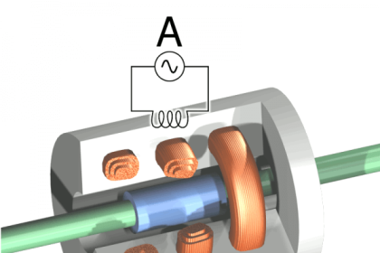
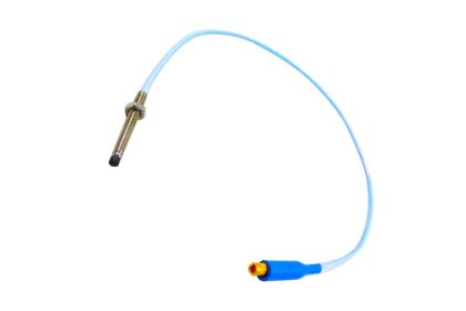
Now, the question of how an eddy-current proximity probe works:

An eddy-current probe works by passing an alternating current through a coil of wire and measuring the coil’s impedance. This impedance changes when the probe is brought near an electrically conductive material and the impedance change is proportional to the physical gap between the coil and the conductive target. The sensing electronics in turn convert this impedance change to a voltage, providing an electrical output directly proportional to physical gap which is directly proportional to vibration.

Also Read: Vibration Sensors Principles & Types

Don't Miss Our Updates
Be the first to get exclusive content straight to your email.
We promise not to spam you. You can unsubscribe at any time.
Invalid email address
You've successfully subscribed !

Continue Reading

Importance of Vibration Measurement
Determine Lifting of Shaft using Proximity Sensor
Bently Nevada Vibration Probes Functional Testing
Vibration Monitoring System Step by Step Troubleshooting Guide
How to do calibration checks of vibration Probe, extension cable and vibration monitor
Bently Nevada 3500 Machinery Protection Systems Hardware Modules
Share This Article
Facebook Whatsapp Whatsapp LinkedIn Copy Link
Share
8 Comments
  • R S Raghavan says:
    October 26, 2016 at 4:05 am

    A very good response from you can say ‘horses mouth’! When I was confronted with vibration monitoring first time way back 35 years or so, I was thinking this has something to do with the corrosion prevention as we do in automobiles.

    Actually I never got satisfactory response from even Bently Nevada techies I had come across. So I left it for some latter day investigation when I could become wiser on material science of turbine casing as well as the probes.

    I came to a sort of conclusion that that it has to do with some history of BN development, perhaps tracing to the then available material for turbine and probe design. I revisited the subject and found your response.

    It was educative.I suppose slowly the stress on -24V should be removed, else people consider this sacred. I do not think there is any PNP based design around alive in industry!! Thanks

    Reply
  • S.muthukumar says:
    July 18, 2017 at 4:50 am

    Thanks sir
    Useful one

    Reply
  • Helery Navas says:
    August 18, 2017 at 1:05 pm

    very good information.

    Reply
  • S.j.patel says:
    August 31, 2017 at 1:39 pm

    Good information regarding vibration monitoring system

    Reply
  • Sivachidambaram B says:
    September 25, 2018 at 7:59 pm

    Sir i want to know why gap voltage set at -10??

    Reply
    • azetou says:
      September 26, 2018 at 6:12 pm

      Please find response to your question in the following link :

      https://www.allinterview.com/showanswers/181270/meant-gap-voltage-vibration-measurement-normally-much-set-and-state-reason.html

      All hail google.

      Reply
  • Bhagwan Singh Lodha says:
    October 8, 2019 at 2:30 pm

    Very nice explain thanks sir

    Reply
  • masoud baqi says:
    January 20, 2021 at 1:07 pm

    thanks , good and nice explain

    Reply

Leave a Reply Cancel reply

Your email address will not be published. Required fields are marked *

Stay Connected

128.3kFollowersLike
69.1kFollowersFollow
210kSubscribersSubscribe
38kFollowersFollow

Categories

Explore More

Bently Nevada Vibration System Verification Procedure
Seismic Transducers Objective Questions
Mechanical Vibration Switch Principle
What is Turbine Supervisory Instrumentation (TSI)?
Advantages & Disadvantages of Different Vibration Sensors
Interview Questions on Vibration Measurement
Types of Sensors used in Vibration Measurement
Root Cause Analysis for Vibration Probe Not Responding

Keep Learning

Proximity Transducer Operation

Proximity Transducer System Operation

Vibration Analysis

Top 100 Vibration Analysis Questions and Answers

tk3 calibration instrument

What is TK-3 Calibrator ?

Basics of Vibration Measurement

Basics of Vibration Measurement

Vibration Probe Commissioning Checklist

Vibration Probe Commissioning Checklist

AND Logic in Bently Nevada Vibration System

AND Logic in Bently Nevada Vibration System

LVDT Principle

Contact Vibration Measurement

Working of Proximitor

Different Types of Turbine Protective Devices

Learn More

DDE Protocol

What is the DDE Protocol?

multi-hole-restriction-orifice-plate

Basics of Restriction Orifice (RO) – Types, Applications, Standards

Thermal Mass Flowmeter Principle

Thermal Mass Flow Meter – Principle, Advantages, Applications

Pump Mechanical Seal and thrust bearing Problem

Pump 3-monthly Seal Leaks threaten entire Plant Shut down Indefinitely

Power System Protection and Relays Questions & Answers

Power System Protection and Relays Questions & Answers

Inspection of Control Valves

Inspection and Test Requirement of Control Valves

Sensor Trim and Output Trim in Smart Transmitter

What is Sensor Trim and Output Trim in Smart Transmitter?

Power Electronics Objective Questions

Thyristor Family Quiz

Menu

  • About
  • Privacy Policy
  • Copyright

Quick Links

  • Learn PLC
  • Helping Hand
  • Part Time Job

YouTube Subscribe

Follow US
All rights reserved. Reproduction in whole or in part without written permission is prohibited.
Welcome Back!

Sign in to your account

Username or Email Address
Password

Lost your password?