We know the benefits of robust PID control Tuning. Increased productivity, decreased equipment strain, and increased process safety are some of the advantages touted of proper PID tuning.
What is often overlooked, though, are the negative consequences of poor PID controller tuning. If robust PID control can increase productivity, then poor PID control can decrease productivity.
If a well-tuned system helps equipment run longer and safer, then a poorly tuned system may increased failure frequency and safety incidents.
The instrumentation professional should be mindful of this dichotomy when proceeding to tune a PID control system. One should never think there is “nothing to lose” by trying different PID settings. Tuning a PID controller is as serious a matter as reconfiguring any field instrument.
PID tuning parameters are easy to access, which makes them a tempting place to begin for technicians looking to improve the performance of a feedback loop.
Another temptation driving technicians to focus on controller tuning as a first step is the prestige associated with being able to tame an unruly feedback loop with a few adjustments to the controller’s PID tuning constants.
For those who do not understand PID control (and this constitutes the vast majority of the human population, even in the industrial world), there is something “magic” about being able to achieve robust control behavior simply by making small adjustments to numbers in a computer (or to knobs in an analog controller).
The reality, though, is that many poorly-behaving control systems are that way not due (at least purely) to a deficit of proper PID tuning values, but rather to problems external to the controller which no amount of “tuning” will solve. Adjusting PID tuning constants as a first step is almost always a bad idea.
This article aims to describe and explain some of the recommended considerations prior to making adjustments to the tuning of a loop controller. These considerations include:
- Identifying operational needs (i.e. “How do the operators want the system to respond?”)
- Identifying process and system hazards before manipulating the loop
- Identifying whether it is a tuning problem, a field instrument problem, and/or a design problem
Identifying operational needs
As defined elsewhere in this article, “robust” control is a stability of the process variable despite changes in load, fast response to changes in setpoint, minimal oscillation following either type of change, and minimal offset (error between setpoint and process variable) over time.
However, these criteria are not equally valued in all processes, and neither are they equally attainable with simple PID control in all processes.
It may be critical, for example, in a boiler water level control process to have fast response to changes in load, but minimal offset over time is not as important. It may be completely permissible to have a persistent 5% error between PV and SP in such a system, so long as the water level does not deviate much over 20% for any length of time due to load changes.
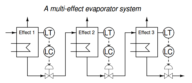
In another process, such as liquid level control inside one stage (“effect”) of a multi-stage (“multieffect”) evaporator system, a priority may be placed upon relatively steady flow control through the valve rather than steady level in the process.
A level controller tuned for aggressive response to setpoint changes will cause large fluctuations in liquid flow rate to all successive stages (“effects”) of the evaporator process in the event of a sudden load or setpoint change, which would be more detrimental to product quality than some deviation from setpoint in that one effect.
Thus, we must first determine what the operational needs of a control system are before we aim to adjust the performance of that control system. The operations personnel (operators, unit managers, process engineers) are your best resources here. Ultimately, they are your “internal customers.” Your task is to give the customers the system performance they need to do their jobs best.
Keep in mind the following process control objectives, knowing that it will likely be impossible to achieve all of them with any particular PID tuning. Try to rank the relative importance of these objectives, then concentrate on achieving those most important, at the expense of those least important:
- Minimum change in PV (dynamic stability) with changes in load
- Fast response to setpoint changes (minimum dynamic error)
- Minimum overshoot/undershoot/oscillation following sudden load or setpoint changes
- Minimum error (PV − SP) over time
- Minimum valve velocity (i.e. minimal effect to upstream or downstream processes)
The control actions best suited for rapid response to load and/or setpoint changes are proportional and derivative. Integral action takes effect only after error has had time to develop, and as such cannot act as immediately as either proportional or derivative.
If the priority is to minimize overshoot, undershoot, and/or oscillations, the controller’s response will likely need to be more sluggish than is typical. New setpoint values will take longer to achieve, and load changes will not be responded to with quite the same vigor. Derivative action may be helpful in some applications to “tame” the oscillatory tendencies of proportional and integral actions.
Minimum error over time can really only be addressed by integral action. No other controller action pays specific “attention” to the magnitude and duration of error. This is not to say that the process will work well on integral-only control, but rather that integral action will be absolutely necessary (i.e. a P-only or PD controller will not suffice).
Minimum valve velocity is a priority in processes where the manipulated variable has an effect on some other process in the system. For example, liquid level control in a multi-stage (multi-“effect”) evaporator system where the discharge flow from one evaporator becomes the incoming flow for another evaporator, is a system where sharp changes in the manipulated variable of one control loop can upset downstream processes:
In other words, an aggressively-tuned level controller on an upstream evaporator (e.g. Effect 1) may achieve its goal of holding liquid level very steady in that evaporator by varying its out-going flow, but it will do so at the expense of causing level variations in all downstream evaporators. Cases such as this call for controller tuning (at least in the upstream effects) responding slowly to errors.
Proportional action will very likely be limited to low gain values (high proportional band values), and derivative action (if any is used at all) should be set to respond only to the process variable, not to error (PV − SP).
This leaves the main work of stabilizing the loop to integral action, even though we know that integral action tends to overshoot following setpoint changes in an integrating process such as liquid level control.
Understand that tuning a PID loop with the goal of minimizing valve motion will result in longer deviations from setpoint than if the controller were tuned to respond faster to process or setpoint changes.
Identifying process and system hazards
When students practice PID control in an Instrumentation program, they usually do so using computer simulation software and/or “toy” processes constructed in a lab environment.
A potential disadvantage to this learning environment is a failure to recognize real problems that may develop when tuning an actual production process.
Rarely will you find a completely isolated feedback loop in industry: generally there are interactive effects between control loops in a process, which means one cannot proceed to tune a loop with impunity.
A very important question to ask the operations personnel before tuning a loop is, “How far and how fast am I allowed to let the process variable increase and decrease?” Processes and process equipment may become dangerously unstable,
For example, if certain temperatures become to high (or too low, as is the case in process liquids that solidify when cold). It is not uncommon for certain control loops in a process to be equipped with alarms, either hard or soft, that automatically shut down equipment if exceeded. Clearly, these “shutdown” limits must be avoided during the tuning of the process loop.
One should also examine the control strategy before proceeding to tune. Is this a cascaded loop? If so, the slave controller needs to be tuned before the master. Does this loop incorporate feedforward action to act on load changes?
If so, the effectiveness of that feedforward loop (gain, dynamic compensation) should be checked and adjusted before the feedback loop is tuned. Are there limits in this loop? Is this a selector or override control strategy? If so, you need to be able to clearly tell which loop components are selected, and which signals are being limited, at any given time.
Another consideration is whether or not the process is in a “normal” condition before you attempt to improve its performance. Ask the operations personnel if this is a typical day, or if there is some abnormal condition in effect (equipment shutdown, re-routing of flows, significantly different production rates, etc.) that might skew the response of the process loop to be tuned.
Once again we see a need for input from the operations personnel, because they know the day-to-day behavior of the system better than anyone else.
Identifying the problem(s)
One of the questions I advise instrument technicians to ask of operators when diagnosing any process problem is simply, “How long has this problem existed?” The age of a problem can be a very important indicator of possible causes. If you were told that a problem suddenly developed after the last night shift, you would be inclined to suspect an equipment failure, or something else that could happen suddenly (e.g. a hand valve someone opened or shut when they shouldn’t have).
Alternatively, if you were told a problem has been in existence since the day the process was constructed, you would be more inclined to suspect an issue with system design or improper installation. This same diagnostic technique – obtaining a “history” of the “patient” – applies to loop tuning as well.
A control loop that suddenly stopped working as it should might be suffering from an instrument failure (or an unauthorized change of controller parameters), whereas a chronically misbehaving loop would more likely be suffering from poor design, bad instrument installation, or a controller that was never tuned properly.
In either case, poor control is just as likely to be caused by field instrument problems as it is by incorrect PID tuning parameters. No PID settings can fully compensate for faulty field instrumentation, but it is possible for some instrument problems to be “masked” by controller tuning. Your first step in actually manipulating the control loop should be a check of instrument health.
Thankfully, this is relatively easy to do by performing a series of “step-change” tests with the controller in manual mode. By placing the controller in manual and making small changes in output signal (remember to check with operations to see how far you are allowed to move the output, and how far you can let the PV drift!), you can determine much about the process and the loop instrumentation, including:
- Whether the PV signal is “noisy” (first turn off all damping in the controller and transmitter)
- How much “stiction” is in the control valve
- Whether the process is integrating, runaway, or self-regulating
- Process gain (and whether this gain is stable or if it changes as PV changes)
- Process lag time and lag degree (first-order versus multiple-order)
- Process dead time
Such an open-loop test might reveal potential problems without pinpointing the exact nature or location of those problems.
For example, a large lag time may be intrinsic to the process, or it may be the result of a poorly-installed sensor (e.g. a thermocouple not pushed to touch the bottom of its thermowell) or even a control valve in need of a volume booster or positioner.
Dead time measured in an open-loop test may also be intrinsic to the process (transport delay), intrinsic to the sensor (e.g. a gas chromatograph where each analysis cycle takes several minutes of time), or it could be the result of stiction in the valve. The only way to definitively identify the problem is to test the instruments themselves, ideally in the field location.
An indispensable tool for identifying loop problems is a trend recorder, showing all the relevant variables in a control loop graphed over time. In order to obtain the best “view” of the process, you need to make sure the graphing trend display has sufficient resolution and responsiveness. If the trend fails to show fine details such as noise in the process, it is possible that the graphing device will be insufficient for your needs.
If this is the case, you may still perform response tests of the loop, but you will have to use some other instrument(s) to graph the controller and process actions.
A modern tool useful for this purpose is a portable computer with a data acquisition device connected, giving the computer the ability to read instrument signal voltages.
Many data graphing programs exist for taking acquired data and plotting it over the time domain. Data acquisition modules with sample rates in the thousands of samples per second are available for very modest prices.
Final precautions
Be prepared to document your work! This means capturing and recording “screen shot” images of process trend graphs, both for the initial open-loop tests and the closed-loop PID trials.
It also means documenting the original PID settings of the controller, and all PID setting values attempted during the tuning process (linked to their respective trend graphs, so it will be easy to tell which sets of PID constants produced which process responses).
If there are any instrument configuration settings (e.g. damping time values in process transmitters) changed during the tuning exercise, both the original values and all your changes need to be documented as well.
As a final word, I would like to cast a critical vote against auto-tuning controllers. With all due respect for the engineers who work hard to make controllers “intelligent” enough to adjust their own PID settings, there is no controller in the world able to account for all the factors described in this article.
Feel free to use the automatic tuning feature of a controller, but only after you have ensured all instrument and process problems are corrected, and after you have confirmed the tuning goal of the controller matches the behavioral goal of the control loop as defined by the operators (e.g. fast response versus minimum overshoot, etc.).
Some people in the automation business are over-confident with regard to the capabilities of auto-tuning controllers. We would all do well to recognize this feature as a tool, and just like any other tool it is only as useful as the person handling it is knowledgeable regarding how and why it works. Wielding any tool in ignorance is a recipe for disaster.






Nicely explained. It is truly practical.
Thanks for sharing insights of PID.
Check the loop from field to control valve
Ensure the controller is in manual mode
Stroke chk the cv o to 100%
Once ok
Then open the cv manually from the controller and see the PV n SV are equal
Adjust the gain at min value
Switch the controller from Man to Auto
Then observe the deviation of PV from SV and adjust the gain accordingly
Once the deviation is min in AM
fine-tune by adjusting Integral and Derivative values