Inst ToolsInst ToolsInst Tools
  • Courses
  • Automation
    • PLC
    • Control System
    • Safety System
    • Communication
    • Fire & Gas System
  • Instrumentation
    • Design
    • Pressure
    • Temperature
    • Flow
    • Level
    • Vibration
    • Analyzer
    • Control Valve
    • Switch
    • Calibration
    • Erection & Commissioning
  • Interview
    • Instrumentation
    • Electrical
    • Electronics
    • Practical
  • Q&A
    • Instrumentation
    • Control System
    • Electrical
    • Electronics
    • Analog Electronics
    • Digital Electronics
    • Power Electronics
    • Microprocessor
  • Request
Search
  • Books
  • Software
  • Projects
  • Process
  • Tools
  • Basics
  • Formula
  • Power Plant
  • Root Cause Analysis
  • Electrical Basics
  • Animation
  • Standards
  • 4-20 mA Course
  • Siemens PLC Course
Reading: What is Integral Flow Orifice Assembly?
Share
Notification Show More
Font ResizerAa
Inst ToolsInst Tools
Font ResizerAa
  • Courses
  • Design
  • PLC
  • Interview
  • Control System
Search
  • Courses
  • Automation
    • PLC
    • Control System
    • Safety System
    • Communication
    • Fire & Gas System
  • Instrumentation
    • Design
    • Pressure
    • Temperature
    • Flow
    • Level
    • Vibration
    • Analyzer
    • Control Valve
    • Switch
    • Calibration
    • Erection & Commissioning
  • Interview
    • Instrumentation
    • Electrical
    • Electronics
    • Practical
  • Q&A
    • Instrumentation
    • Control System
    • Electrical
    • Electronics
    • Analog Electronics
    • Digital Electronics
    • Power Electronics
    • Microprocessor
  • Request
Follow US
All rights reserved. Reproduction in whole or in part without written permission is prohibited.
Inst Tools > Blog > Flow Measurement > What is Integral Flow Orifice Assembly?

What is Integral Flow Orifice Assembly?

Integral Flow Orifice Assembly is used when a Differential Pressure Transmitter has to be directly mounted on the orifice assembly.

Last updated: November 2, 2023 12:36 pm
Editorial Staff
Flow Measurement
2 Comments
Share
3 Min Read
SHARE

Integral Flow Orifice Assembly is used when a Differential Pressure Transmitter has to be directly mounted on the orifice assembly.

Contents
Integral Flow Orifice AssemblyAdvantages of Integral Meter run assembly:Types of Meter Runs

This eliminates the cost of installation of a Differential Pressure Transmitter with impulse piping up to the orifice assembly.

Integral Flow Orifice Assembly

Integral Orifice Assembly

The transmitter is mounted on the orifice assembly through a 3/5 Valve H-type manifold. Available with line sizes of 2″ & below. However, due to the process temperature limits of the transmitter, this assembly cannot be used to process temperatures above 120 degrees Centigrade.

The assembly consists of an orifice plate between two integral blocks having corner taps. Generally, a meter run pipe is recommended with an upstream length of 750mm and a downstream length of 250mm. The pipes are welded to the blocks with end flanges.

Advantages of Integral Meter run assembly:

The use of an integral orifice flow meter will eliminate the three measurement inaccuracies recorded in small orifice line installations.

The Integral orifice-honed body reduces ID uncertainty.

By inserting precision bored upstream and downstream sections of pipe, the velocity profile distortion due to pipe roughness is reduced.

The self-centering design of the Integral Orifice Plate eliminates plate misalignment.

Improves Reliability and Maintenance Costs

The integral orifice flow meter eliminates impulse lines, reducing leak points by over 50% and decreasing start-up time due to the flexibility of numerous process connection options.

The direct mount design minimizes line plugging by eliminating long lines, small-bore ports, and services while providing consistently reliable installations.

  • Accuracy up to ±0.5% of the volumetric flow rate.
  • The integral manifold head allows direct mounting of DP transmitters.
  • Ideal fluid types: liquid, gas, and steam

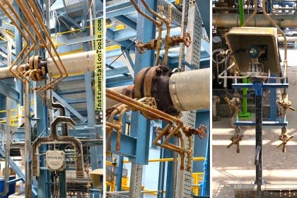
Integral Orifice Assembly with flange union, manifold valve, DP transmitter & end flanges

Integral Orifice Parts

Meter runs are supplied as a complete unit of normally 1M length to ensure the necessary straight pipe length to achieve the highest possible efficiency.

These are available with line sizes mostly below 50mm with a corner tap.

These are used for the measurement of small flow rates precisely where high accuracy of flow rates is required.

Types of Meter Runs

  1. Orifice Flange union with Meter -run.
  2. Orifice flange union with Carrier ring and meter run.

End Connection: Socket Weld, Screwed and Flanged ends with meter run piping suitable to ANSI, IS & DIN flanges.

Reference – prisma-instruments

If you liked this article, then please subscribe to our YouTube Channel for Instrumentation, Electrical, PLC, and SCADA video tutorials.

You can also follow us on Facebook and Twitter to receive daily updates.

Read Next:

  • Advantages of Flow Meter
  • Magnetic Flow Meter Corrosion
  • What is an Orifice Flange?
  • Displacement Flowmeters
  • What is a Dall Tube Flowmeter?
Don't Miss Our Updates
Be the first to get exclusive content straight to your email.
We promise not to spam you. You can unsubscribe at any time.
Invalid email address
You've successfully subscribed !

Continue Reading

Overview of Positive Displacement Flow Meters
Coriolis Mass Flow Meter as a Multi-Variable Transmitter
Open Channel Flow Measurement Principle
Important Factors in Flow Measurement
Flow Meter K-factor and Calculations
Metal Tube Variable Area Flow Meters Principle
Share This Article
Facebook Whatsapp Whatsapp LinkedIn Copy Link
Share
2 Comments
  • M.Umer Irshad says:
    April 22, 2022 at 5:34 pm

    Can compact type integral orifice with Transmitter installed with isolation valves bw TX n sensing integral lines??

    Reply
  • Mi says:
    July 11, 2023 at 2:00 pm

    Your site, your articles are very helpful. Thank you for your understandable description.

    Reply

Leave a Reply Cancel reply

Your email address will not be published. Required fields are marked *

Stay Connected

128.3kFollowersLike
69.1kFollowersFollow
210kSubscribersSubscribe
38kFollowersFollow

Categories

Explore More

What is a Velocity-based Flow Meter?
Rotary Abutment Flow Meters Working Principle and Animation
Ultrasonic Flow Meters Animation
Reasons to Calibrate Different Types of Flow Meters
All About Turbine Meters
Classification of Flow Measurement Techniques
What is a Torbar? – Averaging Pitot Tubes
Difference between Invasive, Non-invasive, Intrusive & Non-intrusive

Keep Learning

Differential Pressure Flow Meters

Short Notes on Differential Pressure Flow Meters

Coriolis Mass Flow Meter Verification Procedure

Prover Tank Calibration and Mass Flow Meter Verification Procedure

V Cone Flow Meter Working Principle

V Cone Flow Meter – Principle, Advantages, Disadvantages

Water Cut Meter

What is Water Cut Meter?

Paddle Wheel Flow Meter

Paddle Wheel Flow Meters – Principle, Advantages, Limitations

W Type Transit Time Flow Meter

Transit Time Flow Meter – Types, Advantages, Disadvantages

Flowmeter Characteristics

Flow Meter Characteristics

Weigh feeders Principle

What is a Weigh Feeder?

Learn More

Electromechanical_Relays Circuit

Relay Loop Back Circuit

How To Choose A Surge Protector?

How To Choose A Surge Protector?

Cut-outs between Platforms or Grating for Field Instruments

Cut-outs between Platforms or Grating for Field Instruments

PLC Program for Valves

PLC Pump Permissive Interlocks

Distributed Control System Architecture for Foundation Fieldbus Field Instruments

What is Foundation Fieldbus (FF) ?

Distributed IO for Siemens PLC

How to Configure Distributed IO in a PLC Project?

Calculate the Magnitude of Hydrostatic Pressure

Calculate the Magnitude of Hydrostatic Pressure

Basics of Electricity Rates

Basics of Electricity Rates

Menu

  • About
  • Privacy Policy
  • Copyright

Quick Links

  • Learn PLC
  • Helping Hand
  • Part Time Job

YouTube Subscribe

Follow US
All rights reserved. Reproduction in whole or in part without written permission is prohibited.
Welcome Back!

Sign in to your account

Username or Email Address
Password

Lost your password?