Inst ToolsInst ToolsInst Tools
  • Courses
  • Automation
    • PLC
    • Control System
    • Safety System
    • Communication
    • Fire & Gas System
  • Instrumentation
    • Design
    • Pressure
    • Temperature
    • Flow
    • Level
    • Vibration
    • Analyzer
    • Control Valve
    • Switch
    • Calibration
    • Erection & Commissioning
  • Interview
    • Instrumentation
    • Electrical
    • Electronics
    • Practical
  • Q&A
    • Instrumentation
    • Control System
    • Electrical
    • Electronics
    • Analog Electronics
    • Digital Electronics
    • Power Electronics
    • Microprocessor
  • Request
Search
  • Books
  • Software
  • Projects
  • Process
  • Tools
  • Basics
  • Formula
  • Power Plant
  • Root Cause Analysis
  • Electrical Basics
  • Animation
  • Standards
  • 4-20 mA Course
  • Siemens PLC Course
Reading: What is a Line Choke or Reactor in a VFD?
Share
Notification Show More
Font ResizerAa
Inst ToolsInst Tools
Font ResizerAa
  • Courses
  • Design
  • PLC
  • Interview
  • Control System
Search
  • Courses
  • Automation
    • PLC
    • Control System
    • Safety System
    • Communication
    • Fire & Gas System
  • Instrumentation
    • Design
    • Pressure
    • Temperature
    • Flow
    • Level
    • Vibration
    • Analyzer
    • Control Valve
    • Switch
    • Calibration
    • Erection & Commissioning
  • Interview
    • Instrumentation
    • Electrical
    • Electronics
    • Practical
  • Q&A
    • Instrumentation
    • Control System
    • Electrical
    • Electronics
    • Analog Electronics
    • Digital Electronics
    • Power Electronics
    • Microprocessor
  • Request
Follow US
All rights reserved. Reproduction in whole or in part without written permission is prohibited.
Inst Tools > Blog > Electrical Basics > What is a Line Choke or Reactor in a VFD?

What is a Line Choke or Reactor in a VFD?

Line choke is an inductance connected to the VFD input or output circuit to protect the VFD from unwanted spikes, transients, and harmonics.

Last updated: September 28, 2022 4:09 pm
Viral Nagda
Electrical Basics PLC Tutorials
2 Comments
Share
4 Min Read
SHARE

In this post, we will see the concept of a line choke or reactor.

Contents
Line Choke in a VFDLine ChokeLoad Reactor

Line choke is an inductance connected to the VFD input or output circuit. It is a component that forms a magnetic field as current flows through it and when the current increases, it limits the increment in current by producing a voltage or emf across it that opposes it.

This protects the VFD from unwanted spikes, transients, and harmonics. The reactor is used on either the input side or output side of the VFD.

When a reactor is used on the input side, it is called a line reactor and when it is used on the output side, it is called a load reactor.

Line Choke in a VFD

What is a Line Choke or Reactor in a VFD

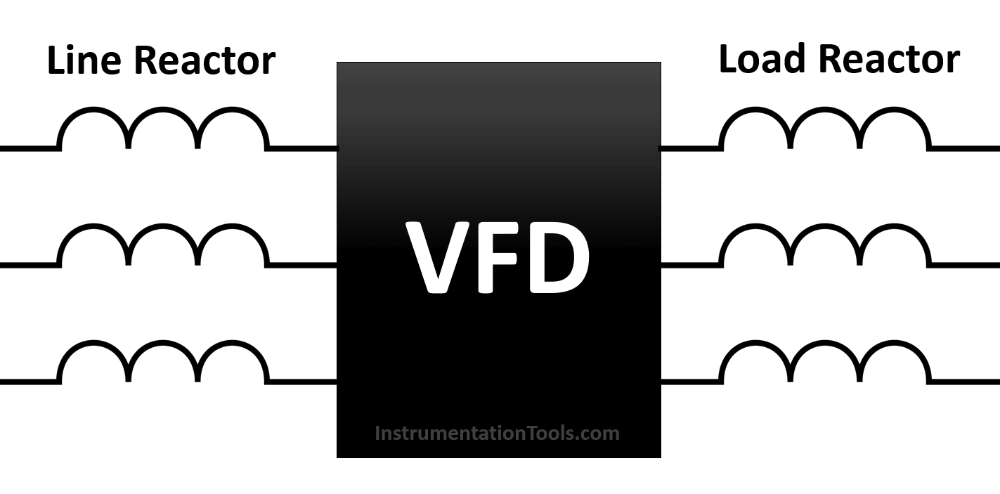
Refer to the above image. The inductance is shown on the input side and the output side is nothing but the line choke. It is normally used for VFD’s which have a rating of more than 1 KVA. Let us understand its basic working.

It is not always necessary that a current wave be sinusoidal. When it is not sinusoidal, it contains harmonics. Harmonics are a large current distortion.

If you see the basic equation of an inductor, it is – V = L (di/dt)

Here, V is the voltage, L is the inductance of the choke or reactor, and (di/dt) is the rate of change of current.

As the current change rate increases, the voltage too increases in proportional to the inductance.

But, this induced voltage has the opposite polarity to that of the applied voltage. This automatically reduces the rate of current change and limits the current applied.

Line Choke

One more theory can be understood here for the output side of VFD. As a high switching frequency is produced at the output of VFD, sharp changes in voltage outputs are reflected sometimes.

This high spikes in voltage can damage the motor circuit or even heat the VFD itself. This can be reduced by using a line choke.

The line choke reduces the peak of the voltage waveform and increases the changing rise time of the signal; to stabilize the final output waveform.

The stabilized waveform will indirectly provide limited current and voltage output to the motor.

Load Reactor

A load reactor is used when the distance between the motor and VFD is very large; mostly 100 feet or more.

Due to long-distance, voltage spikes are amplified more and this can affect the circuit in a large way. So, the line choke will limit this current to a safe limit.

This inductance plays a very important role in protecting the thyristors of the VFD from damage or overheating. Mostly, this device is used when several drives are connected in parallel closely; or the line power supply is imbalanced or largely variable, etc.

In this way, we understood the basic concept of the line choke.

If you liked this article, then please subscribe to our YouTube Channel for Electrical, Electronics, Instrumentation, PLC, and SCADA video tutorials.

You can also follow us on Facebook and Twitter to receive daily updates.

Read Next:

  • What is a Link Box?
  • Static UPS and Rotary UPS
  • Commissioning of VFD Drive
  • DOL Starter Working Principle
  • Motor Forward Reverse Control
Don't Miss Our Updates
Be the first to get exclusive content straight to your email.
We promise not to spam you. You can unsubscribe at any time.
Invalid email address
You've successfully subscribed !

Continue Reading

Partial Discharge in Power Lines and its Detection through Sensors
Examples of PLC Programming using Boolean Functions
Configuration of Siemens VFD Using TIA Portal Start drive
How to do Simulation in Schneider PLC?
PLC Input Output Modules
Single-acting Cylinder OR Logic Operation (PLC and Sensors)
Share This Article
Facebook Whatsapp Whatsapp LinkedIn Copy Link
Share
2 Comments
  • b says:
    July 12, 2023 at 2:13 pm

    in practical oprational case some tims there is harmonices.how we reduce such conditions?the other critical thinkg here on the choking line in what mechanism?auto?
    manually?penumatic? the technology limitation also limtted ,how you can imprve such manner/
    thanks alot.

    Reply
  • Bhanu says:
    August 5, 2023 at 11:18 am

    Thanks for this article,
    I want to design line chokes.
    Can you help me.

    Reply

Leave a Reply Cancel reply

Your email address will not be published. Required fields are marked *

Stay Connected

128.3kFollowersLike
69.1kFollowersFollow
210kSubscribersSubscribe
38kFollowersFollow

Categories

Explore More

How to Automatically Close Pop-up in FactoryTalk View Studio?
Extended Timer Logic in PLC
Factory I/O PLC Automation Training Course (Free)
Workstation Healthiness Checks
PLC Selective Execution of the Application – Example Program
Loop Check of 4-20mA or HART Transmitters
High-end Programmable Logic Controller – Schneider PLC
Unknown Do’s Need to Know as a PLC Programmer

Keep Learning

Car Parking System using PLC Programming

Car Parking System using PLC Programming

Hardwired IO and Serial IO - Differences Explained

Hardwired I/O and Serial I/O – Differences Explained

Basic PLC Alarm Programming Example

Basic PLC Alarm Programming Example

Sequential Operation of Output Bits using Two Push buttons

Sequential Operation of Output Bits using Two Push buttons

What is Loop Checking

What is Loop Checking?

PLC Ladder Logic for Motor Control

PLC Program for Motor Starter

PLC Ladder Logic Example

PLC Ladder Logic Example

Repeat Until Statement in SCL Language

Repeat Until Statement in SCL Language

Learn More

10 Questions on Reforming Furnace Control System

10 Questions on Reforming Furnace Control System

Fundamentals of Digital Systems Quiz

200 Quiz Questions on Fundamentals of Digital Systems

Analog Indicators Objective Questions

Analog Indicators Objective Questions

Industrial Automation Sales and Marketing Tools

Industrial Automation Sales and Marketing Tools

Float-type Level Switch for Sensing Low Oil Level

Float-type Level Switch for Sensing Low Oil Level

Quiz on Sensor Transducer

Quiz on Sensor Transducer

Ion Spectrometers Questions & Answers

Auger Electron Spectroscopy

Hook-up Diagram for Pressure Gauge

What is Instrument Hook Up Diagram ?

Menu

  • About
  • Privacy Policy
  • Copyright

Quick Links

  • Learn PLC
  • Helping Hand
  • Part Time Job

YouTube Subscribe

Follow US
All rights reserved. Reproduction in whole or in part without written permission is prohibited.
Welcome Back!

Sign in to your account

Username or Email Address
Password

Lost your password?