Inst ToolsInst ToolsInst Tools
  • Courses
  • Automation
    • PLC
    • Control System
    • Safety System
    • Communication
    • Fire & Gas System
  • Instrumentation
    • Design
    • Pressure
    • Temperature
    • Flow
    • Level
    • Vibration
    • Analyzer
    • Control Valve
    • Switch
    • Calibration
    • Erection & Commissioning
  • Interview
    • Instrumentation
    • Electrical
    • Electronics
    • Practical
  • Q&A
    • Instrumentation
    • Control System
    • Electrical
    • Electronics
    • Analog Electronics
    • Digital Electronics
    • Power Electronics
    • Microprocessor
  • Request
Search
  • Books
  • Software
  • Projects
  • Process
  • Tools
  • Basics
  • Formula
  • Power Plant
  • Root Cause Analysis
  • Electrical Basics
  • Animation
  • Standards
  • 4-20 mA Course
  • Siemens PLC Course
Reading: Wattmeter
Share
Font ResizerAa
Inst ToolsInst Tools
Font ResizerAa
  • Courses
  • Design
  • PLC
  • Interview
  • Control System
Search
  • Courses
  • Automation
    • PLC
    • Control System
    • Safety System
    • Communication
    • Fire & Gas System
  • Instrumentation
    • Design
    • Pressure
    • Temperature
    • Flow
    • Level
    • Vibration
    • Analyzer
    • Control Valve
    • Switch
    • Calibration
    • Erection & Commissioning
  • Interview
    • Instrumentation
    • Electrical
    • Electronics
    • Practical
  • Q&A
    • Instrumentation
    • Control System
    • Electrical
    • Electronics
    • Analog Electronics
    • Digital Electronics
    • Power Electronics
    • Microprocessor
  • Request
Follow US
All rights reserved. Reproduction in whole or in part without written permission is prohibited.
Inst Tools > Blog > Electrical Theory > Wattmeter

Wattmeter

Last updated: August 8, 2018 4:35 pm
Editorial Staff
Electrical Theory
No Comments
Share
1 Min Read
SHARE

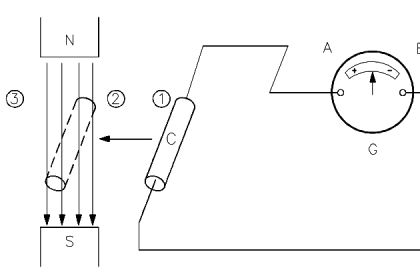
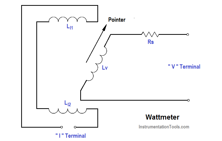
The wattmeter is an instrument which measures DC power or true AC power. The wattmeter uses fixed coils to indicate current, while the movable coil indicates voltage (as shown in below Figure). Coils LI1 and LI2 are the fixed coils in series with one another and serve as an ammeter.

The two ” I ” terminals are connected in series with the load. The movable coil LV , and its multiplier resistor RS , are used as a voltmeter, with the ” V ”  terminals connected in parallel with the load. The meter deflection is proportional to the VI, which is power.

Wattmeter Principle

Wattmeters are rated in terms of their maximum current, voltage, and power. All of these ratings must be observed to prevent damage to the meter.

The below Equation is the mathematical representation of calculating power in a DC circuit.

P = VI     or      P = I2 R

The below Equation is the mathematical representation for calculating power in an AC circuit.

P = VRMS IRMS Cos θ    or      P = I2 R

Don't Miss Our Updates
Be the first to get exclusive content straight to your email.
We promise not to spam you. You can unsubscribe at any time.
Invalid email address
You've successfully subscribed !

Continue Reading

Electrical System Components and Protection Devices
Applying Kirchhoff’s Voltage Law
Series-Wound Motor
Inductor
Power Factor Meter Principle
Wiring Diagram
Share This Article
Facebook Whatsapp Whatsapp LinkedIn Copy Link
Share
Leave a Comment

Leave a Reply Cancel reply

Your email address will not be published. Required fields are marked *

Stay Connected

128.3kFollowersLike
69.1kFollowersFollow
210kSubscribersSubscribe
38kFollowersFollow

Categories

Explore More

Transformer Coil Polarity
Voltmeters
Transformer Losses and Efficiency
Capacitive Time Constant
Single Line Diagram
Transformer Turns Ratio
What is Synchroscope ?
Single Phase AC Induction Motors

Keep Learning

Induction Motor Torque

AC Induction Motor Slip

Transformer Operation Under No-Load

Transformer Operation Under No-Load

induction motor torque versus speed

Induction Motor Torque Versus Slip

Voltage Divider

Voltage Divider

Left-hand Rule for Current Carrying Conductors

Magnetism

Voltage Polarities

Voltage Polarity and Current Direction

DC Motor Connections

DC Motor Connections

D’Arsonval Movement

D’Arsonval Meter Movement

Learn More

Temperature Gauges and Elements Specifications

Temperature Gauges and Elements : Detailed Specifications

Allen-Bradley MicroLogix PLC Wiring

Programmable Logic Controller (PLC) Questions and Answers – 8

Free Safety Instrumented System Training Course

Free Safety Instrumented System Training Course

PLC Commissioning and Testing

PLC Commissioning and Testing Procedure (Programmable Logic Controller)

pi filter Operation

pi filter Operation

microwave flow detector applications

Microwave Flow Sensor – Working Principle and Applications

Car Lifts

Car Lifts – Choosing the Right One for Your Mechanic Shop

Power Factor Meter Principle

Power Factor Meter Principle

Menu

  • About
  • Privacy Policy
  • Copyright

Quick Links

  • Learn PLC
  • Helping Hand
  • Part Time Job

YouTube Subscribe

Follow US
All rights reserved. Reproduction in whole or in part without written permission is prohibited.
Welcome Back!

Sign in to your account

Username or Email Address
Password

Lost your password?