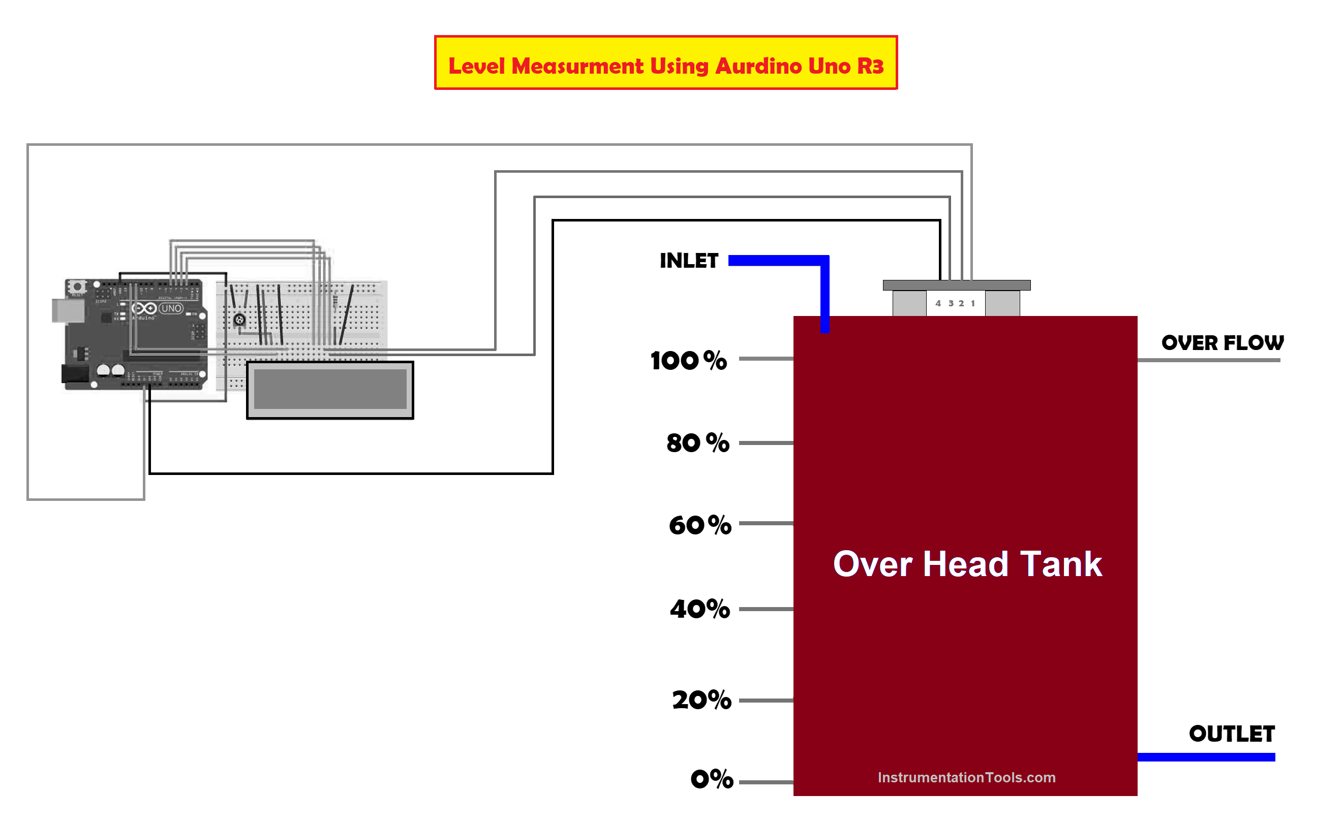
In this article, we will study liquid level measurement in the overhead tank using an Arduino microcontroller.
Level Measurement and Control using Arduino C
To avoid overflow of the tank the level must be measured and corrective action must be taken. Most people use an overhead tank called syntax to store water and the pump arrangement is used to lift the water from the source and use them, but when the tank gets full the water gets exited through an overflow pipe leads to loss of water.
To overcome the losses due to overflow, we have designed a system to measure the level of the tank using an Arduino microcontroller.
What are the components required to measure the level of the liquid?
The required components are
Power Supply
The power supply required for this system is 12 V DC.
Ultrasonic Trans-receiver
- The ultrasonic Trans-receiver HC-SR04 is used to transmit an ultrasonic wave.
- This is used because the human ear can hear the sound frequency around 20Hz to 40 kHz.
- The ultrasonic sensor has 4 pins namely VCC, TRIGGER, ECHO, AND GROUND respectively.
- The ultrasonic transmitter transmits the signal in the air in one direction and the start timing is launched.
- And the signal returns immediately when an obstacle is encountered in the path.
- The velocity of the ultrasonic wave is 340m/s.
- The system works on the phenomenon of ECHO of sound.
- The pulse is sent for about 10 microseconds to trigger the module.
- The signal after striking or hitting the obstacle is captured by the receiver.
- The distance from the obstacle to the sensor is calculated using the formula D= (T*S)/2.
- The pin details of HC-SR02
- Pin No 1 VCC 5V Supply
- Pin No 2 TRIGGER Pulse Input
- Pin No 3 ECHO Pulse Output
- Pin No 4 GND 0V Ground
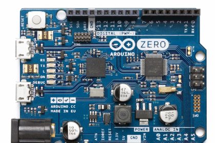
Arduino Uno R3 microcontroller
- The Microcontroller is a small computer on a single IC that includes Processor, memory, and Input and Output Peripherals.
- The Arduino Uno is a Microcontroller board based on the ATmega328.
- It has 14 digital input/output pins (of which 6 can be used as PWM outputs), and 6 analog inputs.
- It is a 16 MHz crystal oscillator with a USB interface connection and a power jack, an ICSP header, and a reset button.
- It can easily be connected to the computer via USB Port.
- It can be easily powered through a power Jack using a 5V AC-to-DC adapter or battery.
- Arduino Uno has its Integral Development Environment (IDE) that uses C-programming language.
- Some of the Technical Specifications of Arduino Uno are listed below
- Input Voltage (recommended) 7-12V
- DC Current per I/O Pin 40 mA
- DC Current for 3.3V Pin 50 mA
- Flash Memory 32 KB of which 0.5 KB is used by the boot loader
- SRAM 2 KB
- EEPROM 1 KB
- Clock Speed 16 MHz
Liquid Crystal Display
- The Display unit RG1602A consists of 16 pins:
- PIN 1 is the VSS or Ground pin.
- PIN 2 is the VDD that provides a 5-volt DC supply to the Arduino Board.
- PIN 3 is V0 which controls the brightness of the display through a variable potentiometer.
- PIN 4 is the RS pin that selects Command / Data to the LCD. If RS is low, the command is sent, if RS is High Data is sent to LCD.
- PIN 5 is the R / W pin which selects the mode for LCD
- PIN 6 is the E pin that enables the writing to the registers or the next 8 data pins
- Pin 7 – Pin 14 D0 to D7 These Pins send 8-bit data to the Registers.
- Pin 15 is Anode (A) and
- Pin 16 (A) and Cathode (K) are for the LED backlight.
Pin Details of Display unit RG1602A.
How does the measurement system work?
The system working is as follows
- The ultrasonic trans-receiver HC-SR04 transmits an ultrasonic signal of frequency 40 kHz through TRIGGER pin the Transmitter for the surface to be detected.
- The signal will bounce after hitting the surface reflects back with a delay of 10 ms, and is received through the ECHO pin the receiver of HCSR04 respectively.
- As a response, it will send an 8-cycle sonic pulse that travels at a speed of sound and is received in the ECHO pin.
- The signal received from the ECHO pin is 2X times the transmitted signal from the TRIGGER pin.
- The ultrasonic trans-receiver HC-SR04 measures the distance up to the range of 2 cm to 150 cm with an accuracy of 3mm.
- The signal is traveled through the air medium with a speed of 340 m/s. If there is an obstacle found in its path it will reflect considering the travel time and speed of the sound.
- Let us consider an object which is at a distance N from the sensor then the speed is 340m/s.
- The time requires to calculate the duration of wave travel is given by
Time = Distance /Speed
- The distance can be calculated using the relation
Distance = (Time * Speed)/2.
= (Time * 0.0342)/2.
What programming language is required to compose the program?
Usually, this program is written in the Arduino C program which is similar to a C program.
LIST OF PROGRAMS
Program 1 “Testing of Ultrasonic Trans-Receiver HC-SR04”
#define echoPin 7 // Echo Pin
#define trigPin 8 // Trigger Pin
#define LEDPin 13 // Onboard LED
int maximumRange = 200; // Maximum range needed
int minimumRange = 0; // Minimum range needed
long int duration, distance; // Duration used to calculate distance
void setup()
{
Serial.begin (9600);
pinMode(trigPin, OUTPUT);
pinMode(echoPin, INPUT);
pinMode(LEDPin, OUTPUT); // Use LED indicator (if required)
}
void loop()
{
digitalWrite(trigPin, LOW);
delayMicroseconds(2);
digitalWrite(trigPin, HIGH);
delayMicroseconds(2);
digitalWrite(trigPin, LOW);
duration = pulseIn(echoPin, HIGH);
distance = duration / 58.2;
if (distance >= maximumRange)
{
Serial.println(“out of area”);
digitalWrite(LEDPin, HIGH);
}
else if (distance <= minimumRange)
{
Serial.println(“within limit”);
digitalWrite(LEDPin, LOW);
} }
Program to measure and indicate the status level
#include <LiquidCrystal.h>
#define trigger 7
#define echo 8
int Range1=0;
int Range2 = 4;
int Range3 = 8;
int Range4 = 12;
int Range5 = 16;
int Range6= 20;
LiquidCrystal.h lcd(12,11,5,4,3,2);
float time=0,level=0,distance=0;
void setup()
{
lcd.begin(16,2);
pinMode(trigger,OUTPUT);
pinMode(echo,INPUT);
lcd.setCursor(0,1);
lcd.clear();
}
void loop()
{
lcd.clear();
digitalWrite(trigger,LOW);
delayMicroseconds(2);
digitalWrite(trigger,HIGH);
delayMicroseconds(10);
digitalWrite(trigger,LOW);
delayMicroseconds(2);
time=pulseIn(echo,HIGH);
distance=time*340/20000;
lcd.clear();
lcd.print(“LEVEL:”);
lcd.print(distance);
lcd.print(“cm”);
lcd.setCursor(0,1);
if (distance <= Range1)
{
lcd.print(“OVERFLOW“);
}
else if (distance <= Range2)
{
lcd.print(“LEVEL VERY HIGH”);
}
else if (distance >= Range3)
{
lcd.print(“LEVEL HIGH “);
}
else if (distance >= Range4)
{
lcd.print(“LEVEL NORMAL”);
}
else if (distance >= Range5)
{
lcd.print(“LEVEL LOW”);
}
else if (distance >= Range6)
{
lcd.print(“LEVEL VERY LOW PUMP ON “);
}
delay(1000);
}