Increasing the reliability of safety loop performance is one of the important target concerns of safety system actions. During the implementation of safety loops, based on SIL study results, the Instrumentation and Control (I&C) Team may use different tricks to increase the total reliability of safety loops.
One of these tricks that may be used to increase reliability is the voting concept. Regardless of the SIL Study subject, the Voting Concept was usually used in Package Safety Systems in different forms. Although the Voting Concept has detailed calculation supports in the SIL Study, we will try to explain how such a concept can increase safety loops with simple words and we will try to investigate some applications in Package Safety Systems (especially focused on Rotating Machinery Packages).
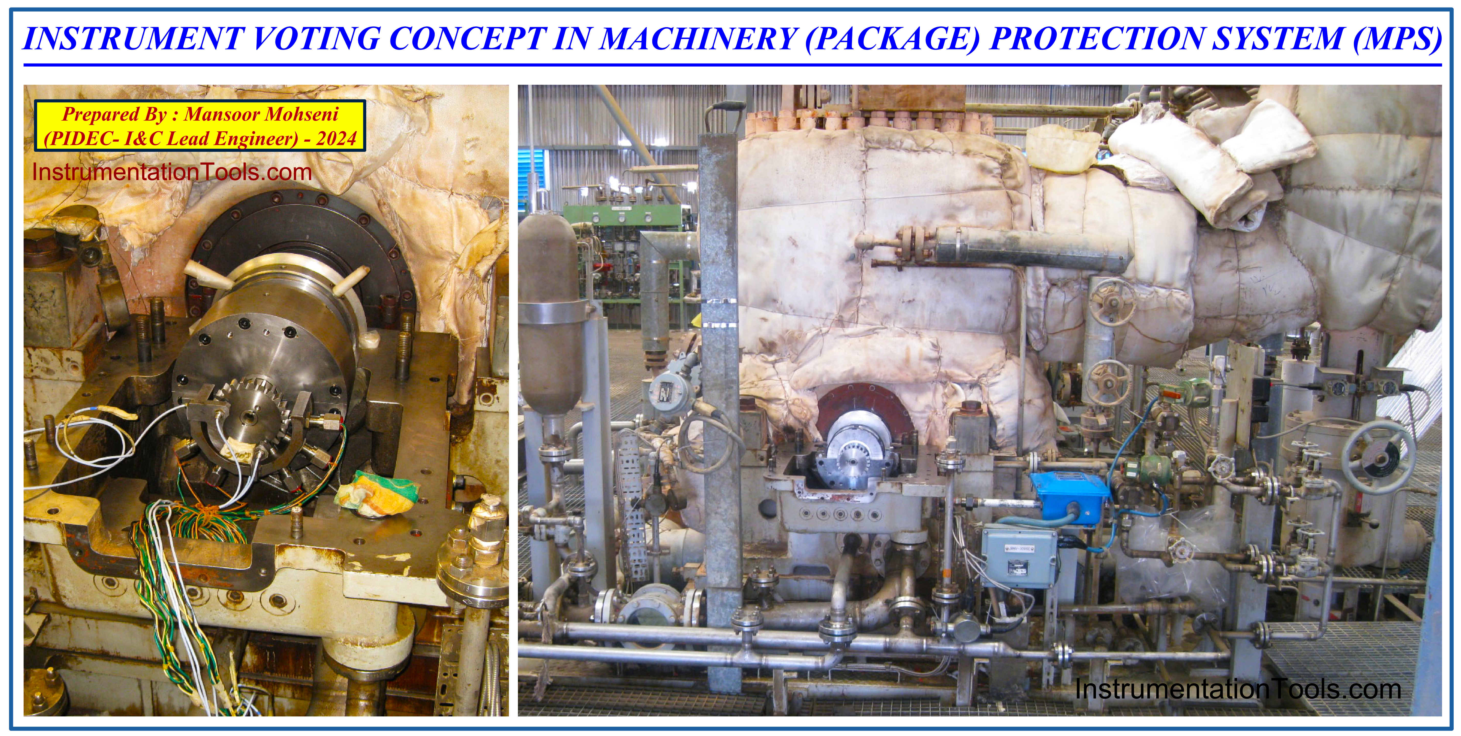
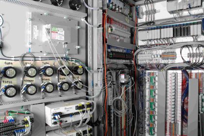
Figure-1: Instrument Voting concept applied in Machinery (Package) Protection System (MPS).
Safety Loop Reliability
Safety loops mainly include the Initiator (Measuring Instrument), Safety (Logic Solver) System, and Final Actuator (See Figure 2). The safety system (Logic Solver) is usually selected from the best performance systems that inherently have rigid resistance to failures due to more expensive system components or use some compensations to decrease the failure rate due to possible problems. However such system reliability shall be studied separately and is out of concern of this article.
Let us focus on the role of instruments in safety loop performance. We expect each safety loop to have the right actions in the case of process upsets which are measured in that loop. On the other hand, the initiator shall detect the process upset and produce the relevant signal for Logic Solver actions.
If the initiator doesn’t detect the process upset due to its (instrument) damage or failure, the Logic Solver cannot provide suitable actions and so the total loops will fail and accordingly, the Process Plant may have big process damage crashes.
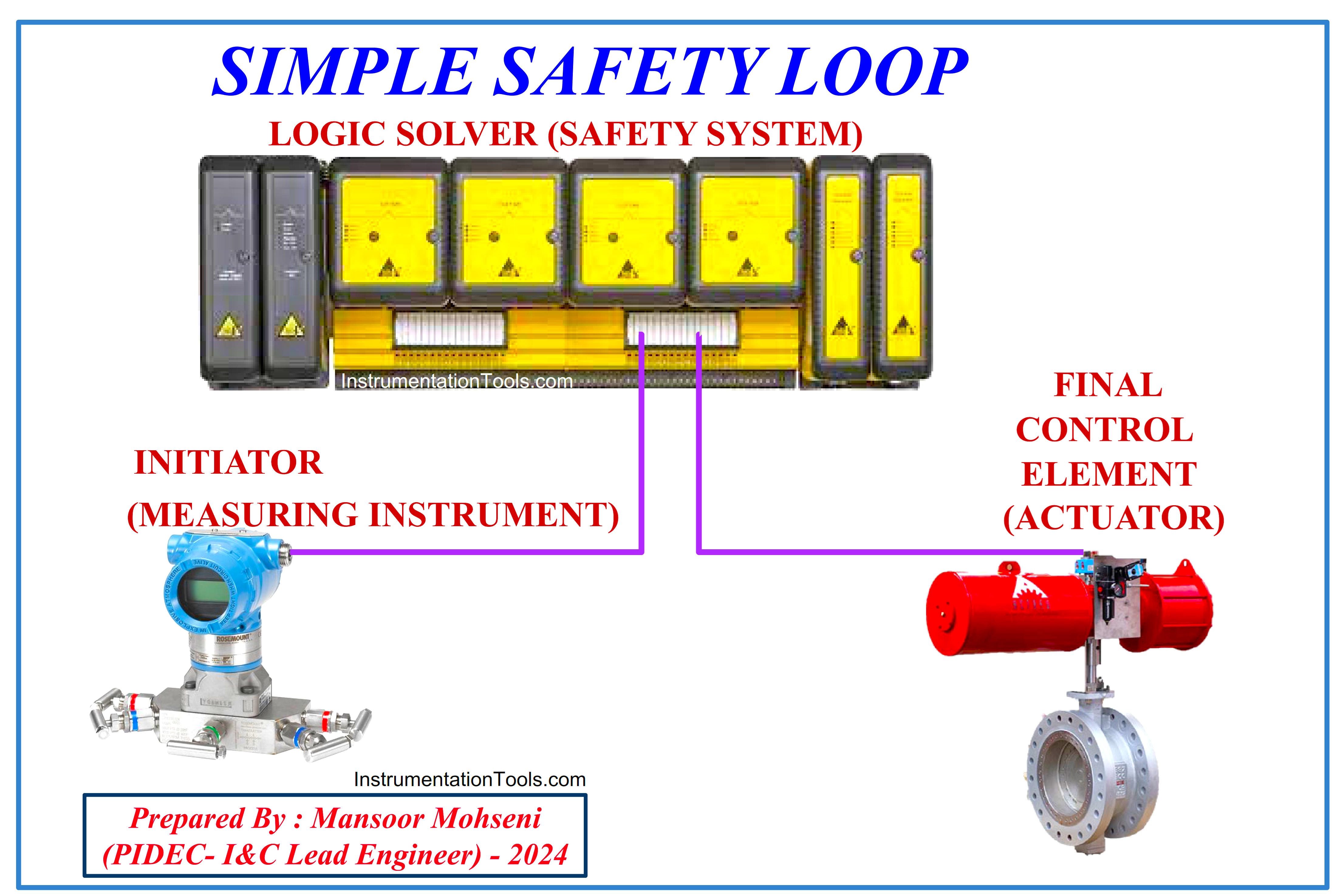
Figure 2: Simple Safety Loop Elements
In other forms of instrument damage or failure, it may create a signal showing the process upset while the process is really in normal conditions. In this case, Logic Solvers will have action on this wrong signal and so it makes a shutdown command. This shutdown command which is called Spurious Shutdown is wrong and will stop the process of normal operations, and it is equal to a plant production stop which will have the waste of profits. It shall be noted that in most of the process plants, after any shutdown activation. Some activities and reset functions may be required which need considerable time (which will have effects on the waste of profits accordingly). So Spurious Shutdown shall not have occurred or the possibility of such an event shall be minimized.
Due to Instrument Signal Reliability, we need the instrument to create the right (correct) signal completely based on process plant conditions. On the other hand, the Probability of Failure on Demand (PFD) of the instrument shall be as much as a low value (about zero), and also probability of occurrence of a Spurious Shut down should lead to zero too. In fact, the first probability will have great effects on the safety loop reliability while the second probability will have great effects on plant availability.
In order to increase the Instrument Reliability and Process Availability, we shall select the best instruments (which are made with the best components and design with minimum failure rate in the market) for safety loops. Of course, such instruments are more expensive than others. Safety loops will be investigated in the SIL (Safety Integrity Level) study and the failure rates of each instrument will be considered in relevant calculations. Sometimes the subject safety loop may be so critical that even if we select the best instrument available in the market, still we cannot reach the required safety loop reliability. In such cases, we may increase the total reliability of safety loops or process availability by using some compensation tricks.
Now, we try to be familiar with one of these tricks, using extra instruments, and try to find the results of different function arrangements of extra instruments without any SIL calculation complexities.
Instrument Voting in Safety Loop
As mentioned above and Figure 3 shows, we may use extra instruments at the initiator position of the safety loop, and combine their signals via different configurations or arrangements. The detailed results of each configuration are mentioned in tabular format in Figure 4 and explained below.
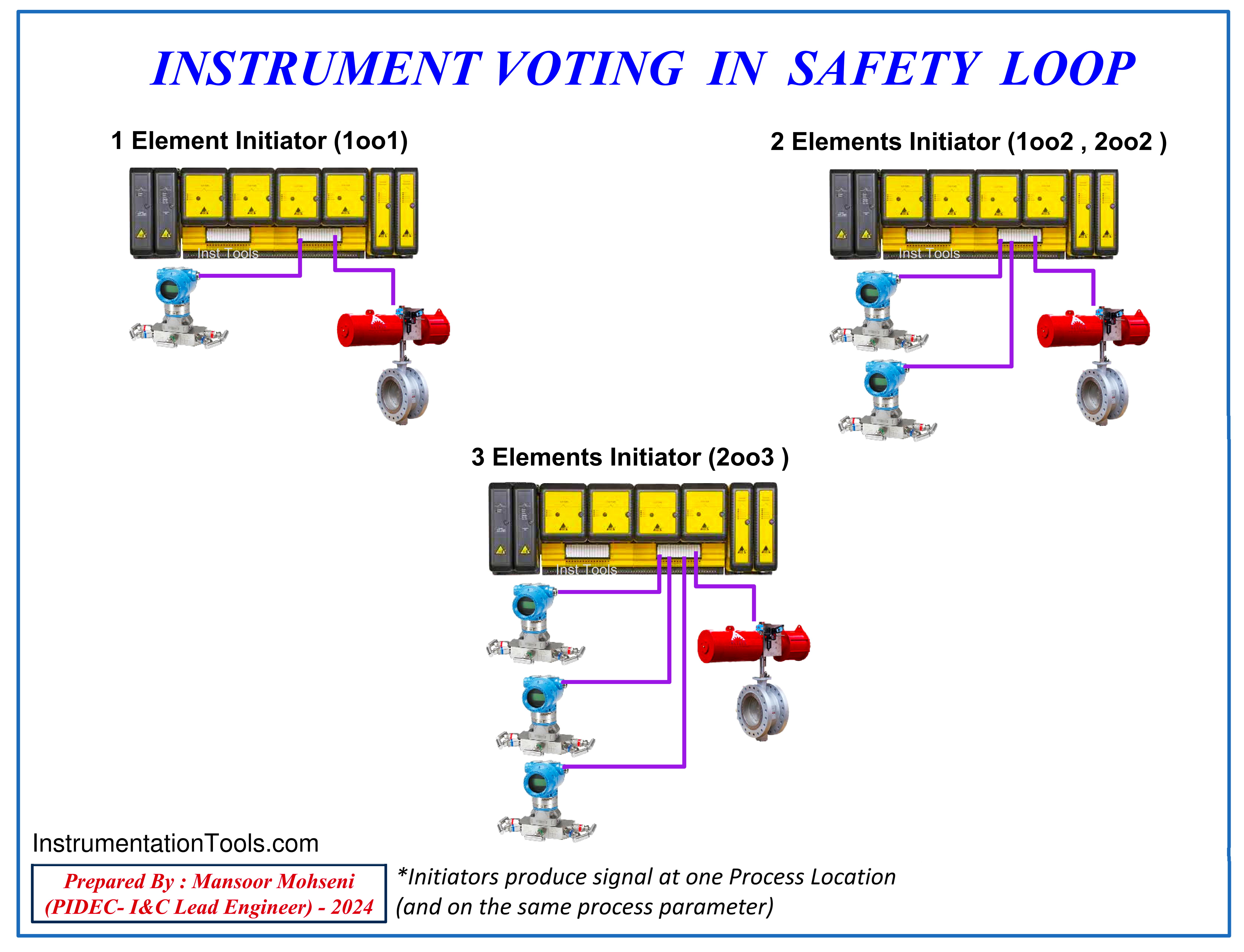
Figure 3: Three Different Forms of Instrument Voting in Safety Loop
For simplicity of our study, in all cases, we will consider the same failure conditions for instruments and also we use a failure model just as a fixed instrument signal (please notice that the failure cases may be more complex with different probabilities). By such consideration, each faulty instrument signal may have a right or wrong signal due to process condition (Normal or Upset) while the healthy instrument signal will follow the process condition.
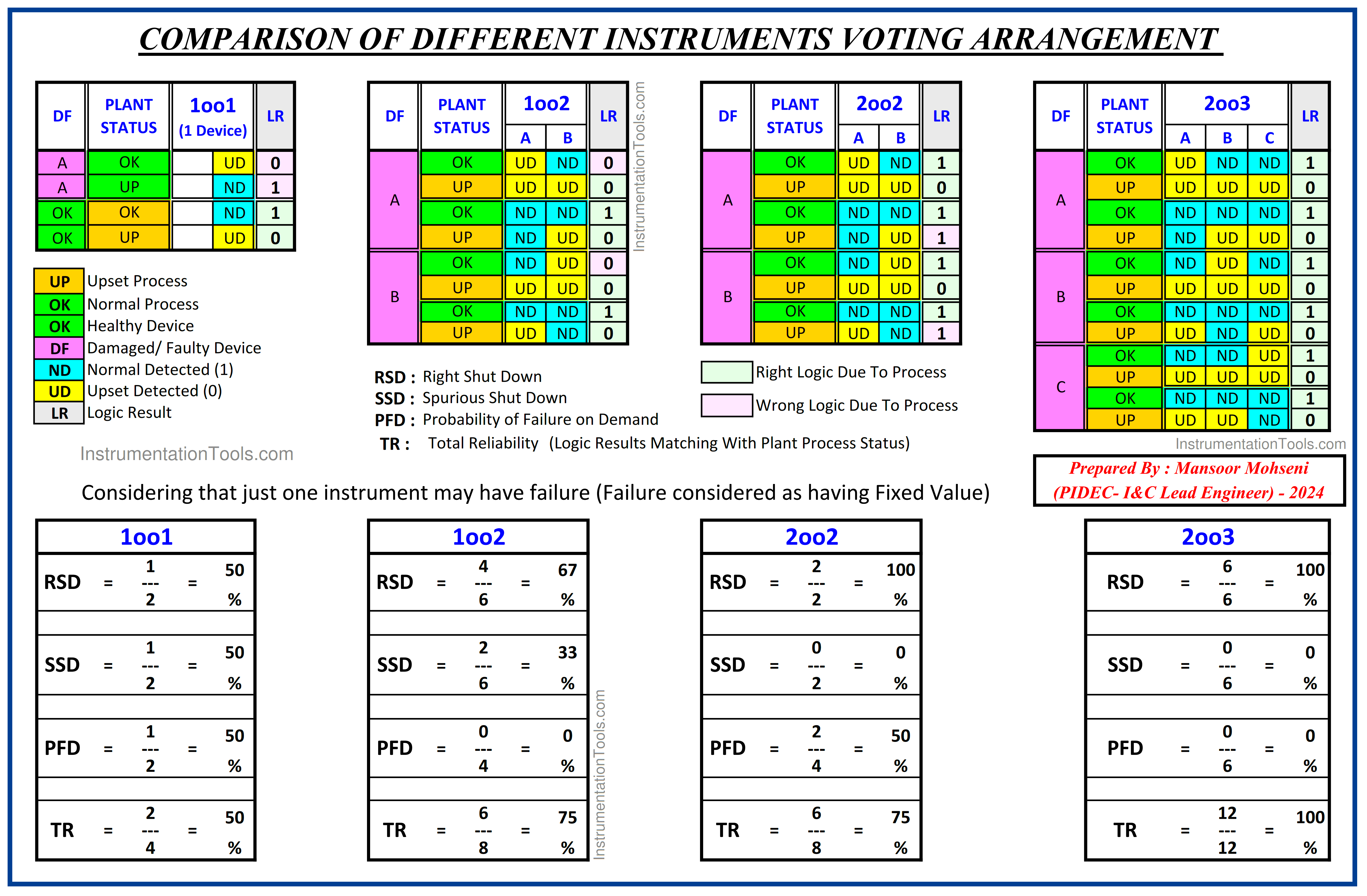
Figure 4: Comparison of Three Different Forms of Instrument Voting Arrangement in Safety Loop with a simple case of one instrument initiator.
It shall be noted that we will consider the failure occurrence of just one instrument in the study of each case. It is clear that the second instrument failure at the same time will have a very low probability and the calculation is not so easy for our study.
1oo1 arrangement
The 1oo1 case is relevant to a simple safety loop with just one instrument as initiator and without any extra instruments. As figure-4 shows the result of such an arrangement will be:
Right Shutdown Probability = 50%
Spurious Shutdown = 50%
Probability of Failure on Demand = 50%
Total Reliability = 50%
1oo2 arrangement
For the 1oo2 case, we have an extra instrument and the logic solver will make a shutdown command if one of the two instrument signals announces the process condition as Upset.
As figure-4 shows the result of such an arrangement will be:
Right Shutdown Probability = Better than a simple case
Spurious Shutdown = Less than a simple case
Probability of Failure on Demand = Very good due to simple case
Total Reliability = Better than a simple case
2oo2 arrangement
For the 2oo2 case, we have an extra instrument and the logic solver will make a shutdown command just if both instrument signals announce the process condition as Upset.
As figure-4 shows the result of such an arrangement will be:
Right Shutdown Probability = Better than a simple case
Spurious Shutdown = Very good due to simple case
Probability of Failure on Demand = About the simple case
Total Reliability = Better than a simple case
2oo3 arrangement
For the 2oo3 case, we have two extra instruments and the logic solver will make a shutdown command just if at least two of the instrument signals announce the process condition as Upset.
As figure-4 shows the result of such an arrangement will be:
Right Shutdown Probability = Very good due to simple case Spurious Shutdown = Very good due to simple case
Probability of Failure on Demand = Very good due to simple case
Total Reliability = Very good due to simple case
As we can see the best result will be using 3 instruments in 2oo3 format, while we shall notice that more extra instruments will have more cost, and so such format can be (legally) applicable for special critical cases. Also in some physical situations (especially in packages), there is not enough space to install 3 instruments at the same location (for all safety loops) so this format cannot be applicable.
If we add one instrument to a simple case loop, we will have two format options. If we use the 1oo2 format we will have better safety reliability but we may have more spurious shutdowns. If we use the 2oo2 format we don’t have spurious shutdowns, but we will have less safety reliability in the case of a Process Upset on making the required shutdown.
So if the simple case instruments may have more damage/ fault possibility and its signal is not so important we can add an additional instrument in the format of 2oo2 to increase plant availability. On the other hand, if the instrument signal is very important for making a shutdown (even the probability of a spurious shutdown may be more and acceptable) we shall add another instrument with the format of 1oo2 (which will have more safety reliability).
SIL Study calculations can approve the above explanations by more exact values, but as mentioned, we tried to find the comparison results by simple words, since package safety systems (requirements /specifications/ standards) used such facilities in the past regardless of the SIL Study subject. In the following, we will see some applications of the Instrument Voting concept in Rotary Machine (Package) Protection (Safety) Systems.
Median Selection Function
When we use switch-type instruments, the output value of the voting function of instrument signals can be easily understandable, but if we use Analog type instruments, the relevant output function may not be easily found, since the analog instruments may have different values due to calibration (or exact range transfer).
However, the voting function will have effects on produced switch points of comparison settings (of analog signals) and so the output may be activated by some difference margins on time. If the calibration of instruments is not so far away from each other, such time margins may not have great effects on safety function loop output.
For making signal validation between three analog signals, usually other functions such as the “Median Selection Function” may be used as shown in Figure-5.
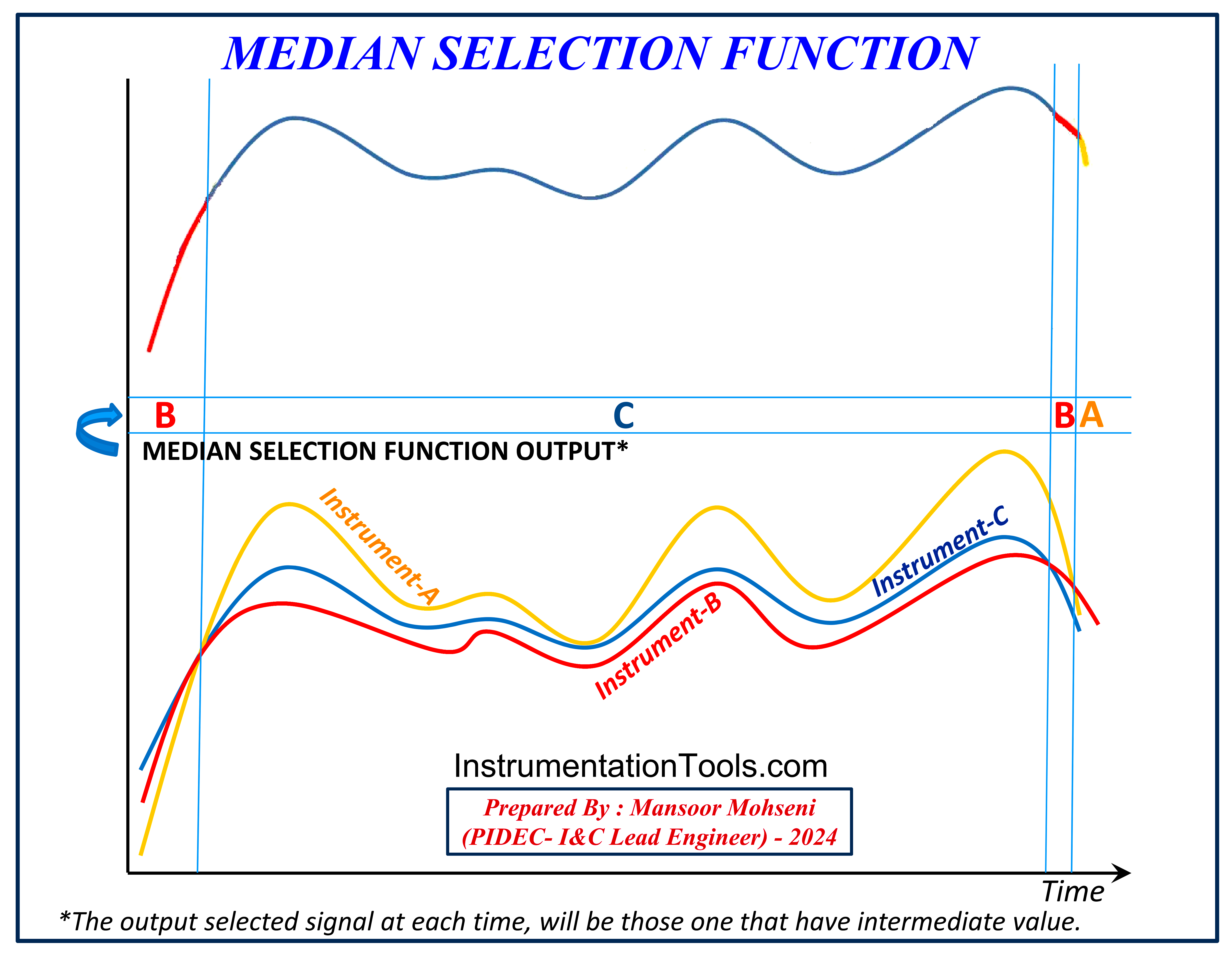
Figure-5: Median Selection Function (Sample Example)
The output selected signal of Median Function at each time will be those that have intermediate value. Probably this signal will be much more valid than two other signals, and always one of the other two signals will have a value greater than or equal to the median selected one, and the other signal will have a value less than or equal to the median selected one.
So if we make a decision action on comparison setting (alarm or trip) on the median selected output, it will be near to (at least) one of the other two signals. This decision is approximately the same as the 2oo3 voting output signal.
Since in some packages the analog signal of 3 installed instrument positions will be important for control and monitoring (with valid signal) too, so usually Median Selection Function block has been preferred over the 2oo3 function block.
If we return to Figure-5 again and investigate for 2oo3 action on process upset values (high or low) we can see the result is very similar to the decision on the Median selected output.
Application of Instrument Signal Voting in Machinery Protection System (MPS)
Figure 6 shows one typical sample P&ID of a Machinery Protection (Safety) System (MPS) of a complex Turbine-Compressor Package, and as it is clear different types of Instrument Signal Voting are used in such package safety systems.
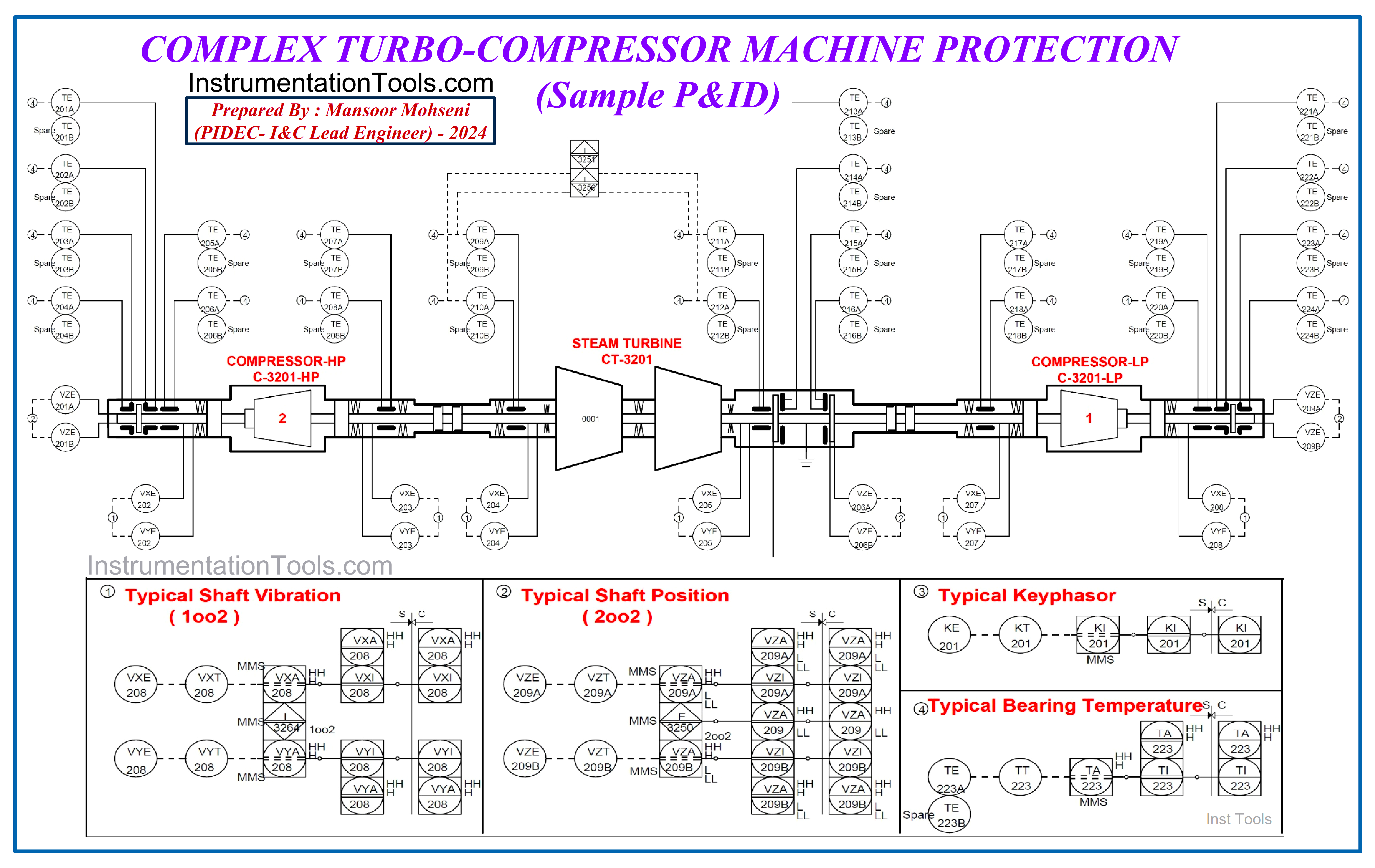
Figure-6: Sample P&ID of Turbo-Compressor Machine Protection System (MPS)
Shaft Radial Vibration Sensors
As we can see typical shaft radial vibration sensors are used in 1oo2 format, and if one of these instruments detects the upset condition, the safety system (logic solver) will take action. It shall be noticed that although both sensors are located in the same location, their signals are not necessarily the same.
In fact, based on Figure-7 these two sensors are used to detect the exact upset vibration as a vector around the shaft orbit, and their signals for normal conditions are near each other, but in upset conditions except just for limited cases, their signals will have different values.
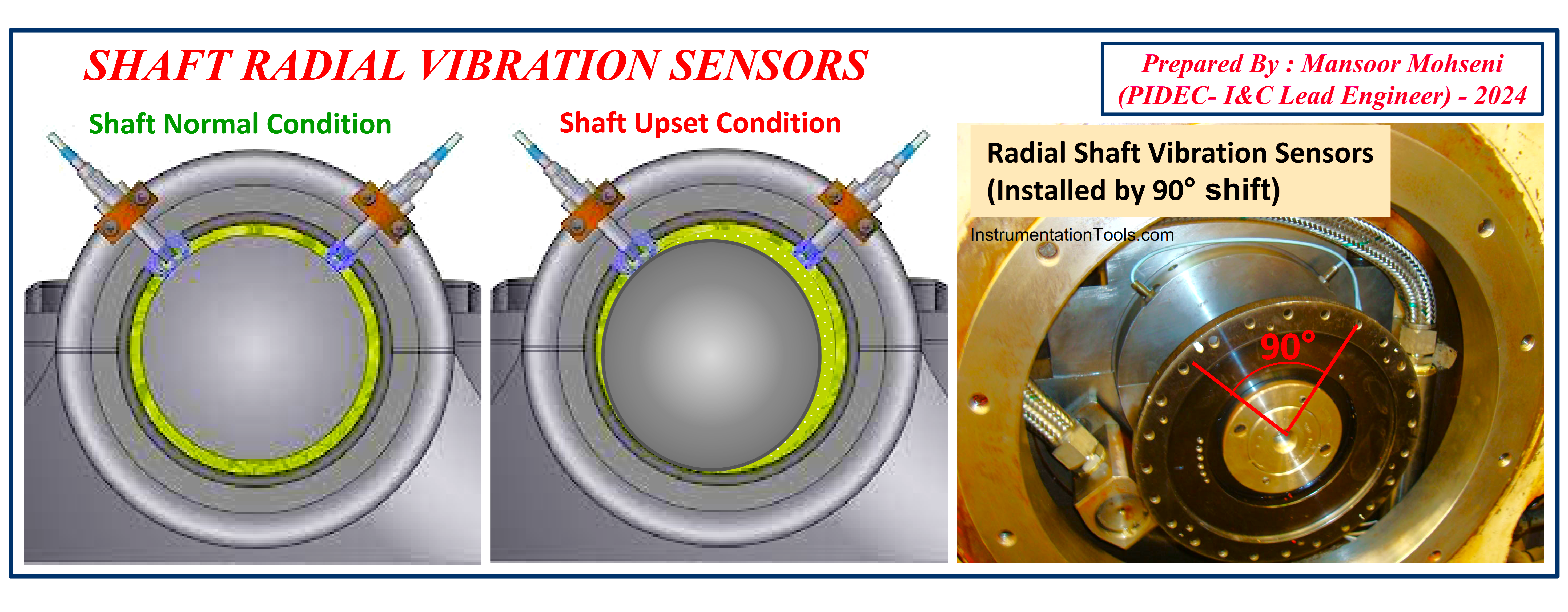
Figure-7: Shaft Radial Vibration Sensors are installed by 90° shift.
However since the radial vibration sensors detect upset conditions at one longitudinal shaft position and the shaft vibration (upset) has a critical role in the healthiness (safety) of the package, the signals of these two sensors shall be considered as 1oo2. Also since the healthiness of at least one sensor is mandatory the proposed logic for such protection may be similar to Figure-8.
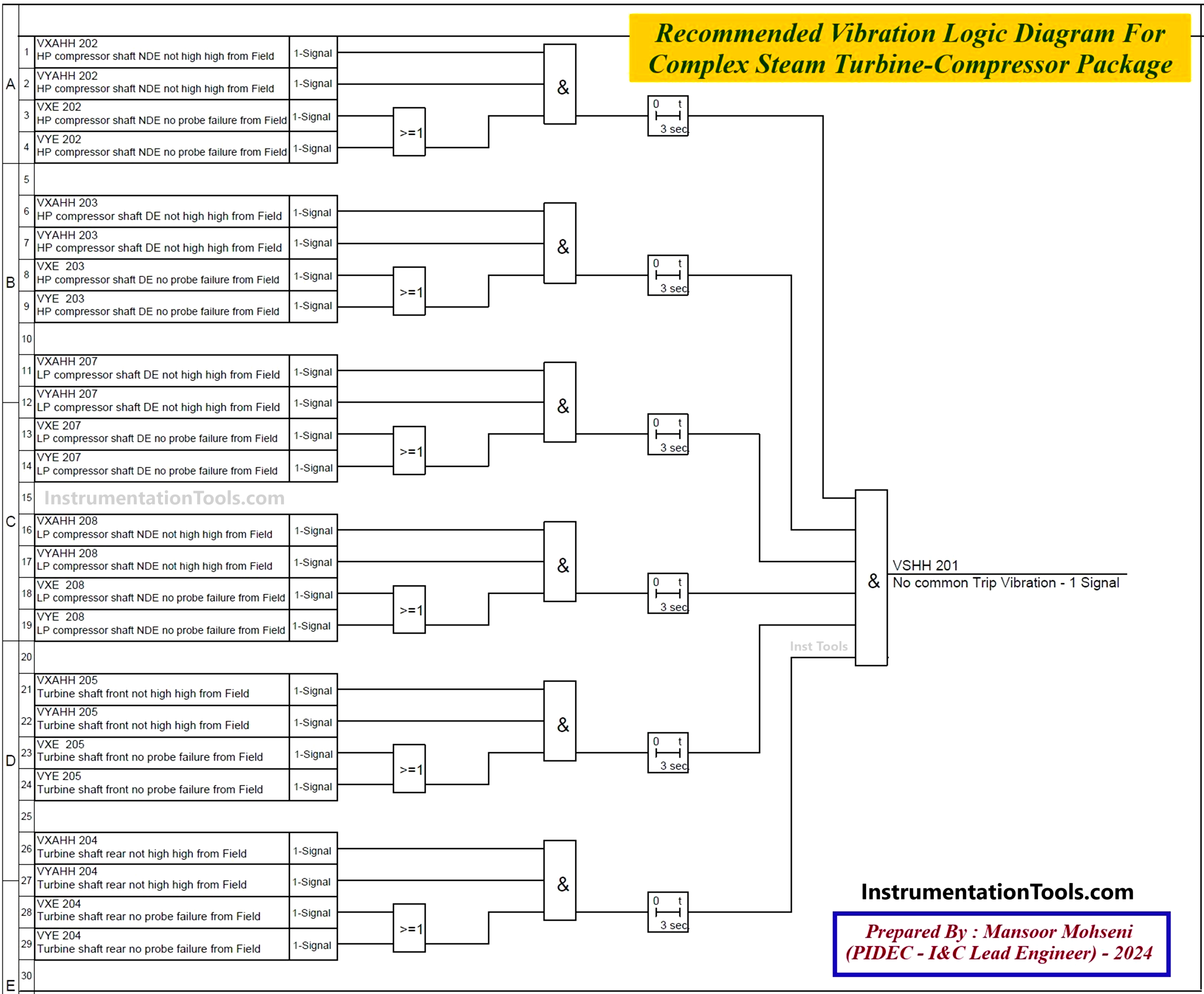
Figure-8: Proposed Protection Logics for Package Vibration Trip (Shutdown).
Shaft Axial Position Sensors
Shaft axial position is detected by 2 sensors, but since the upset condition of such position rarely occurs, in order to reduce the spurious shutdown, these two sensors are considered as 2oo2 format (see Figure-9).
Temperature Protection Sensors
For the protection of the package from over-temperature conditions, some temperature probes are installed on the machine for monitoring, but usually, such sensors may not have automatic (logic) action or if they have, usually are considered as 2oo2 format. It shall be noted that over-temperature cannot occur suddenly and so operators will have enough time to make compensation actions.
However, if it is required to make automatic action they are considered as 2oo2 format to guarantee prevention of spurious shutdown. Since such temperature probes may have a big probability of failure, and replacement of such sensors in the package is not easy, so usually each temperature probe (position) has two sensors and one of them is as spare (See again Figure-6).
Over-Speed Protection
When the driver of the package is a Turbine (Steam or Gas), one of the most dangerous upset conditions is Over-Speed, and to detect such abnormal conditions the 3-speed detection sensors are used in the form of 2oo3 format (See Figure-9). As we concluded before by such a format we will have more reliable safety loop actions while we have no spurious shutdown.
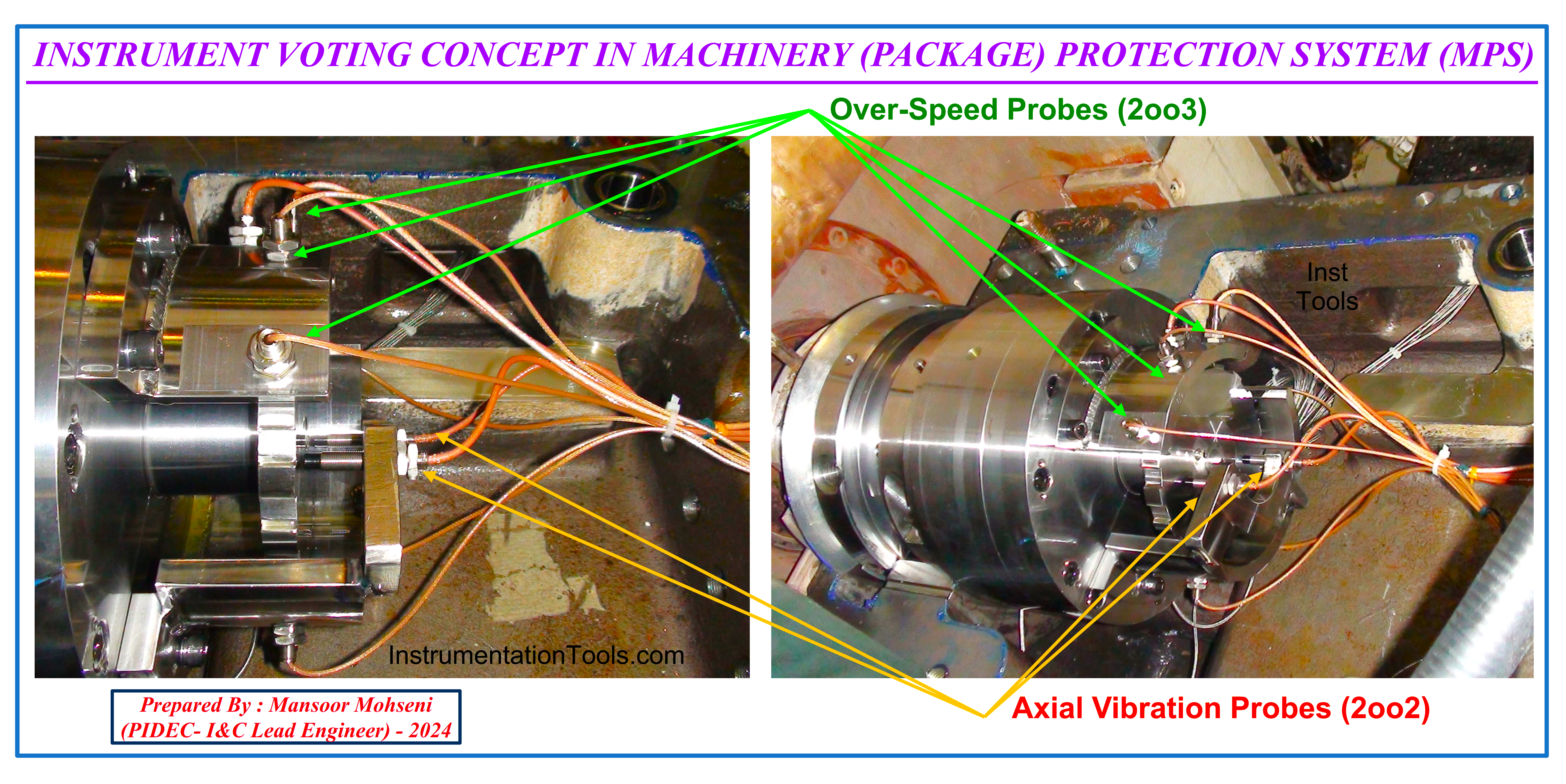
Figure-9: Shaft Axial Position and Turbine Over-Speed Protection Sensors.
Due to the exact speed detection of the shaft turbine (by counting the probe signal) and producing extra facilities (such as one sensor test, final trip valve checking, or start-up override test), Over-Speed Protection will be implemented by separate hardware (system).
Low Lube Oil Pressure Protection
The lube oil pressure has a critical role in package protection (safety), and so the measuring initiator of such parameter is considered by 3 sensors in the form of a median selection function (Figure-10 and Figure-11). As explained above the median selection function can be considered as 2oo3 voting of instruments.
It shall be noted that these sensors are considered for the trip (shutdown) function of the package and it is separated from another pressure measuring device for starting the auxiliary oil pump. However, usually, such instruments are installed on the Local Gauge Board for better operator actions while the measuring point on the lube oil header will be connected to sensors by suitable tubing (See Figure-11).
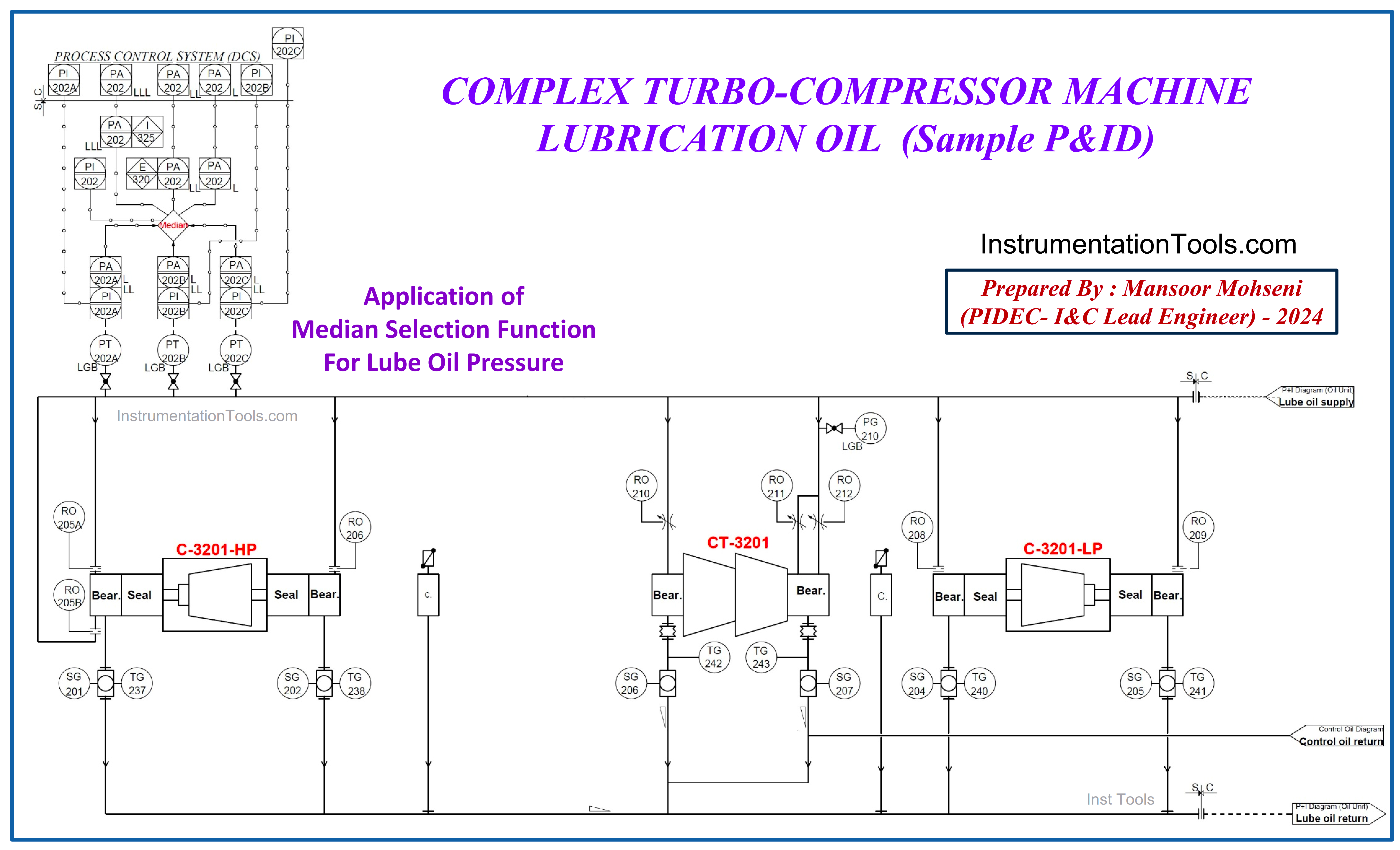
Figure-10: Median Selection Function of Lube Oil Pressure (Sample P&ID).
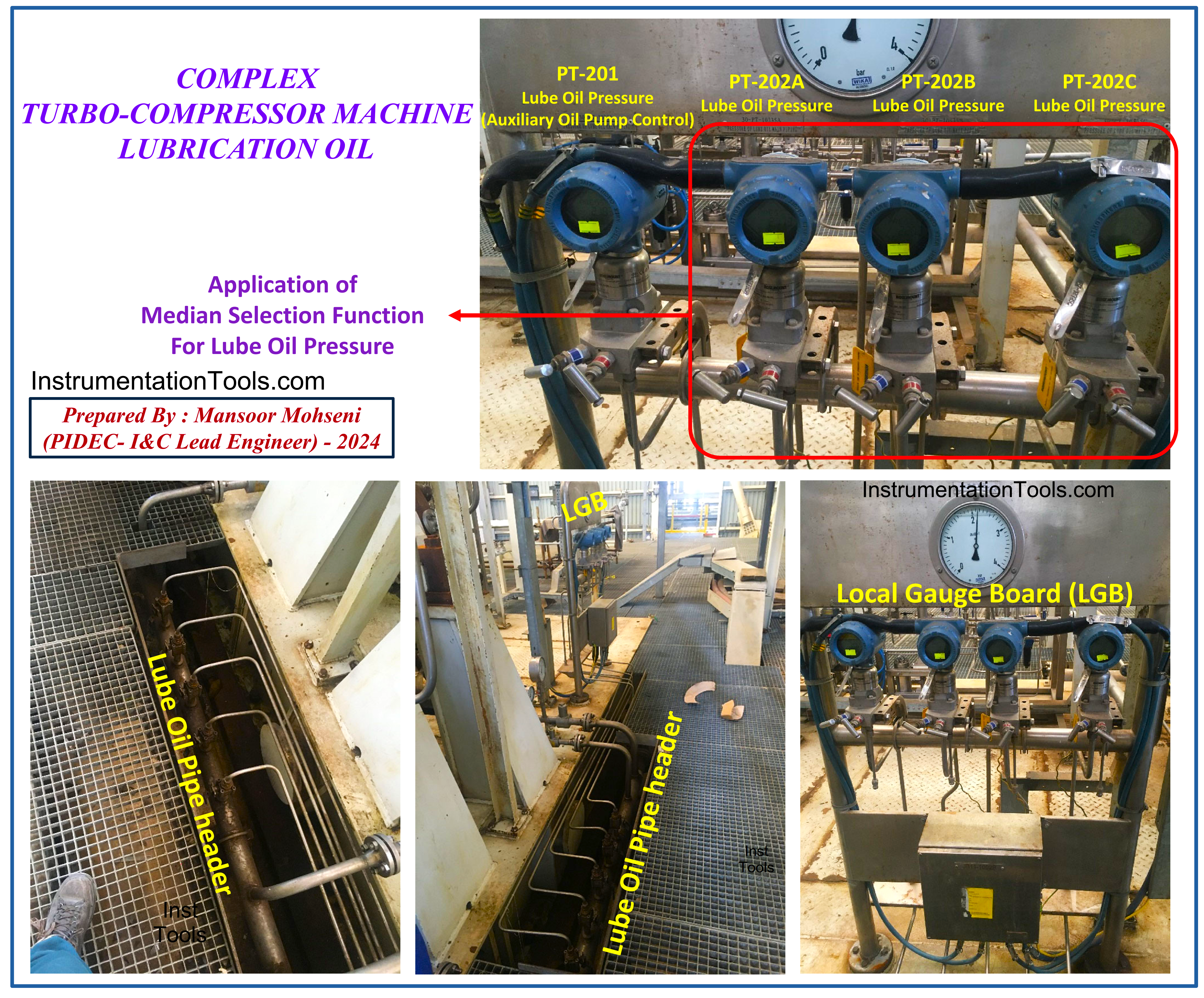
Figure-11: Median Selection Function of Lube Oil Pressure (Installed Sensors).
Seal Gas Pressure Protection
Seal Gas protection of compressor packages is another example of using sensors by Median Selection Function arrangement (equal to 2oo3). Figure 12 shows a sample P&ID of such protection for a complex package.
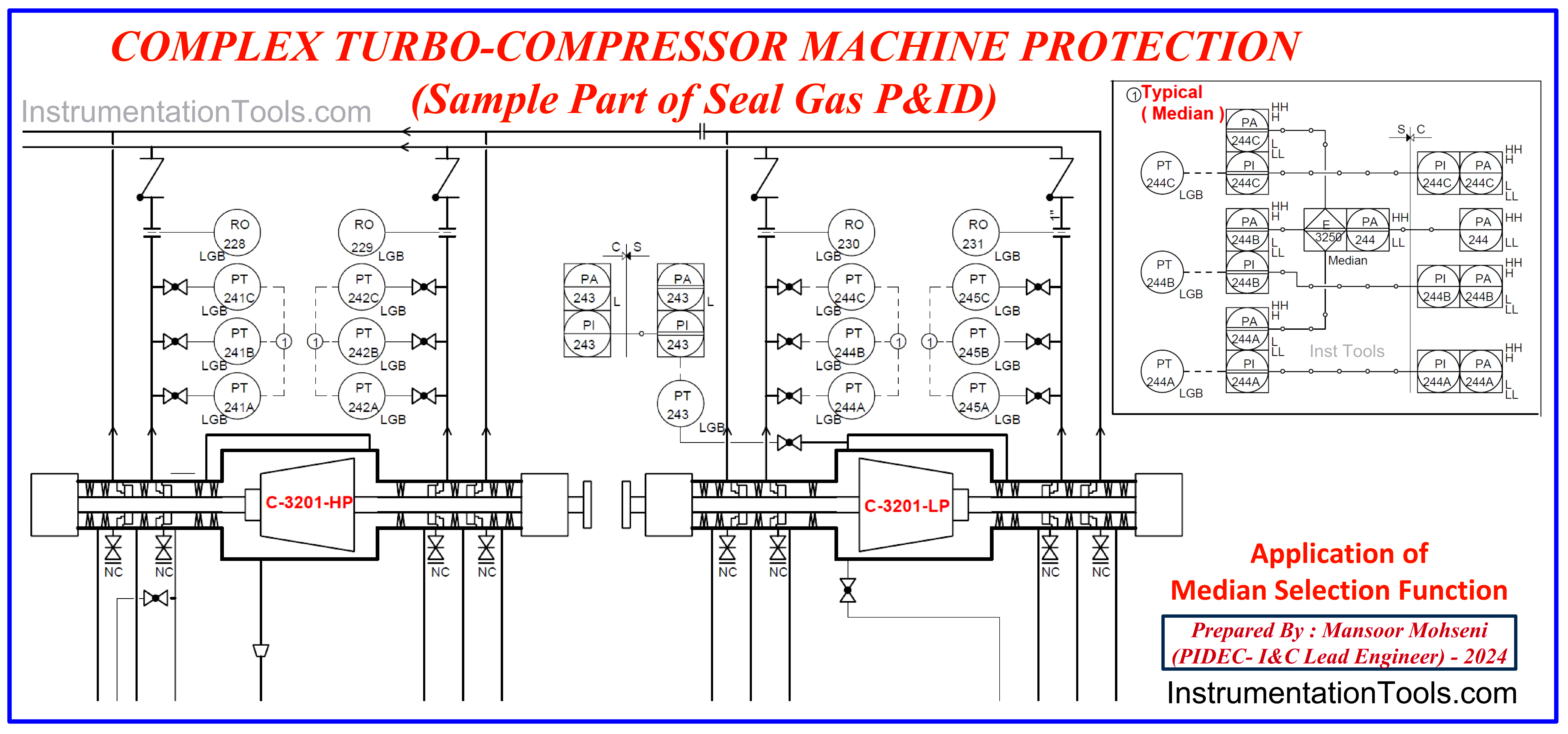
Figure-12: Median Selection Function of Seal Gas Pressure (Sample P&ID).
Conclusion
Using extra sensors (instruments) as initiators of important safety loops while using suitable voting functions can increase the safety loop reliability or plant availability. Such improvement can be approved by SIL calculations, but such subject can be found by simple words too. Packages (machinery) used such improvement tricks from the past (regardless of SIL Study). Some examples of such instrument voting in package safety systems were reviewed in this article.
Also, it was found that the best format of instrument voting is 2oo3 (more safety loop reliability and no spurious shutdown), but due to extra cost or physical limitations (spaces), such tricks are usually used just for important safety loops.
References:
- Package System Architecture Instrumentation
- Turbine Compressor System Architecture
- Instrumentation Engineer in Process Plant Project
- System Architecture and Process Control Systems
