Inst ToolsInst ToolsInst Tools
  • Courses
  • Automation
    • PLC
    • Control System
    • Safety System
    • Communication
    • Fire & Gas System
  • Instrumentation
    • Design
    • Pressure
    • Temperature
    • Flow
    • Level
    • Vibration
    • Analyzer
    • Control Valve
    • Switch
    • Calibration
    • Erection & Commissioning
  • Interview
    • Instrumentation
    • Electrical
    • Electronics
    • Practical
  • Q&A
    • Instrumentation
    • Control System
    • Electrical
    • Electronics
    • Analog Electronics
    • Digital Electronics
    • Power Electronics
    • Microprocessor
  • Request
Search
  • Books
  • Software
  • Projects
  • Process
  • Tools
  • Basics
  • Formula
  • Power Plant
  • Root Cause Analysis
  • Electrical Basics
  • Animation
  • Standards
  • 4-20 mA Course
  • Siemens PLC Course
Reading: Voltmeters
Share
Font ResizerAa
Inst ToolsInst Tools
Font ResizerAa
  • Courses
  • Design
  • PLC
  • Interview
  • Control System
Search
  • Courses
  • Automation
    • PLC
    • Control System
    • Safety System
    • Communication
    • Fire & Gas System
  • Instrumentation
    • Design
    • Pressure
    • Temperature
    • Flow
    • Level
    • Vibration
    • Analyzer
    • Control Valve
    • Switch
    • Calibration
    • Erection & Commissioning
  • Interview
    • Instrumentation
    • Electrical
    • Electronics
    • Practical
  • Q&A
    • Instrumentation
    • Control System
    • Electrical
    • Electronics
    • Analog Electronics
    • Digital Electronics
    • Power Electronics
    • Microprocessor
  • Request
Follow US
All rights reserved. Reproduction in whole or in part without written permission is prohibited.
Inst Tools > Blog > Electrical Theory > Voltmeters

Voltmeters

Last updated: August 7, 2018 9:40 pm
Editorial Staff
Electrical Theory
No Comments
Share
3 Min Read
SHARE

A simple DC voltmeter can be constructed by placing a resistor (RS), called a multiplier, in series with the ammeter meter movement, and marking the meter face to read voltage (as shown in Figure).

Voltmeters are connected in parallel with the load (RL) being measured.

All About Voltmeter

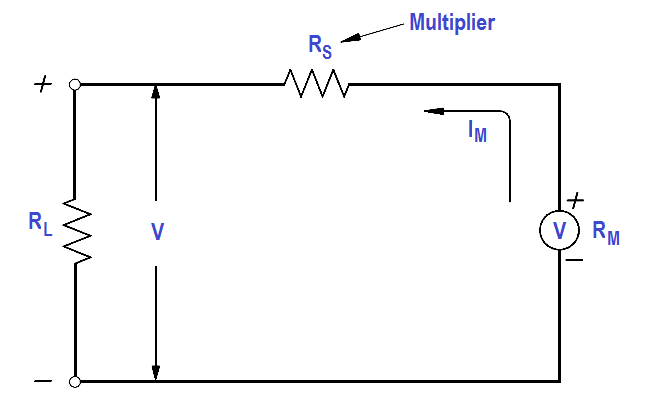
Figure : Simple DC Voltmeter

When constructing a voltmeter, the resistance of the multiplier must be determined to measure the desired voltage. The Equation is a mathematical representation of the voltmeter’s multiplier resistance.

V = ImRs + ImRm
ImRs = V – ImRm

voltmeter multiplier resistance formula

where

V = voltage range desired
Im = meter current
Rm = meter resistance
Rs = multiplier resistance or series resistance

Example:

A 2 mA meter movement with internal resistance of 25 ohms is to be constructed as a voltmeter. What value must the series resistance be to measure full scale voltage of 100 volts?

Solution :

voltmeter multiplier resistance formula

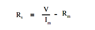
Since Rm is negligibly low, then

Rs = V/Im

Rs = 100 / (2×10⁻³)

Rs =  50kΩ

When a voltmeter is connected in a circuit, the voltmeter will draw current from that circuit. This current causes a voltage drop across the resistance of the meter, which is subtracted from the voltage being measured by the meter. This reduction in voltage is known as the loading effect and can have a serious effect on measurement accuracy, especially for low current circuits.

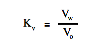
The accuracy of a voltmeter (Kv ) is defined as the ratio of measured voltage when the meter is in the circuit (Vw) to the voltage measured with the meter out of the circuit.

The below Equation is a mathematical representation of the accuracy of a voltmeter, or true voltage (Vo).

accuracy of a voltmeter formula

Meter accuracy can also be determined by comparing the relationship between the input and circuit resistances using Ohm’s Law as described below.
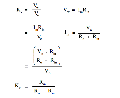
Meter accuracy

where

Im = meter current
Vo = true voltage
Ro = circuit resistance
Rin = input resistance of the voltmeter
Vw = indicated voltage
Kv = meter accuracy

Example:

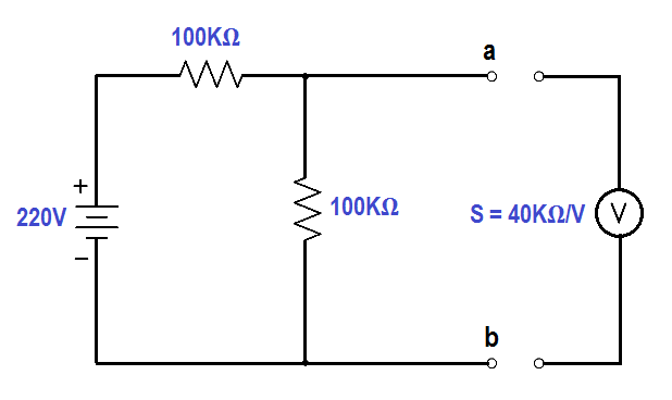
A voltmeter in the 100 volt range with a sensitivity of 40 KΩ/V is to measure the voltage across terminals ab.

Measuring Circuit Voltage

Find :

  1. Vo , true voltage
  2. Vw , indicated voltage
  3. Kv , meter accuracy

Solution :

Find Vo , true voltage

Vo =  { 100 KΩ / (100 KΩ + 100 KΩ) } x 220 volts

Vo = 110 volts

Find Vw , indicated voltage

Ro = (100 x 100) / (100 + 100) = 50KΩ

Rin = S V = 40KΩ x 100 = 4.4 MΩ

Vw = Rin / (Ro + Rin )

Vw = { 4.4MΩ / (50KΩ + 4.4MΩ) } 110 volts

Vw = 108.9 volts

Find Kv , meter accuracy

Kv = Vw / Vo

Kv = 108.9/110

Kv = 0.99 or 99%

Don't Miss Our Updates
Be the first to get exclusive content straight to your email.
We promise not to spam you. You can unsubscribe at any time.
Invalid email address
You've successfully subscribed !

Continue Reading

DC Circuit Analysis Loop Equations
Schematic Diagram
Starting a Synchronous Motor
Inductance and Inductive Reactance
Ampere Hour Meter
Unbalanced 3 Phase Loads
Share This Article
Facebook Whatsapp Whatsapp LinkedIn Copy Link
Share
Leave a Comment

Leave a Reply Cancel reply

Your email address will not be published. Required fields are marked *

Stay Connected

128.3kFollowersLike
69.1kFollowersFollow
210kSubscribersSubscribe
38kFollowersFollow

Categories

Explore More

Resistance in Parallel Circuits
Calculate Power in Parallel RL Circuit
DC Generator Internal Losses
Power Factor Meter Principle
Simplified Formulas for Parallel Circuit Resistance Calculations
Voltage Polarity and Current Direction
Power Factor
Electric Circuit : Open & Short Circuits

Keep Learning

Left-Hand Rule for Current-Carrying Conductors

DC Motor Theory

Air Circuit Breaker Principle

High Voltage Circuit Breaker Principle

Phase angle

AC Generation Analysis : Effective Values, Phase Angle and Frequency

DC Generator

DC Generator

Calculate Power in Series RC Circuit

Calculate Power in Series RC Circuit

Voltage and Current Phase Relationships in an Inductive Circuit

Voltage and Current Phase Relationships in an Inductive Circuit

Electron Flow Through Battery

Batteries Theory

Capacitor and Symbols

Capacitance

Learn More

Layer-2 and Layer-3 Network Switches

Layer-2 and Layer-3 Network Switches

Control Loops Multiple Choice Questions

Control Loop Multiple Choice Questions

Electrical Machines Objective Questions

Electrical Machines MCQ Series 19

conductivity transmitter

Conductivity Transmitter Calibration Procedure

Top 10 Podcasts about Electronics

Top 10 Podcasts about Electronics

Redundant Power Supply

How Does Redundant Power Supply Work?

Structured Text Selector Machine Logic

Write a PLC Program for Selector Machine using Structured Text

Retrieve from memory card

How to Retrieve PLC Project From Memory Card?

Menu

  • About
  • Privacy Policy
  • Copyright

Quick Links

  • Learn PLC
  • Helping Hand
  • Part Time Job

YouTube Subscribe

Follow US
All rights reserved. Reproduction in whole or in part without written permission is prohibited.
Welcome Back!

Sign in to your account

Username or Email Address
Password

Lost your password?