Inst ToolsInst ToolsInst Tools
  • Courses
  • Automation
    • PLC
    • Control System
    • Safety System
    • Communication
    • Fire & Gas System
  • Instrumentation
    • Design
    • Pressure
    • Temperature
    • Flow
    • Level
    • Vibration
    • Analyzer
    • Control Valve
    • Switch
    • Calibration
    • Erection & Commissioning
  • Interview
    • Instrumentation
    • Electrical
    • Electronics
    • Practical
  • Q&A
    • Instrumentation
    • Control System
    • Electrical
    • Electronics
    • Analog Electronics
    • Digital Electronics
    • Power Electronics
    • Microprocessor
  • Request
Search
  • Books
  • Software
  • Projects
  • Process
  • Tools
  • Basics
  • Formula
  • Power Plant
  • Root Cause Analysis
  • Electrical Basics
  • Animation
  • Standards
  • 4-20 mA Course
  • Siemens PLC Course
Reading: 18 Temperature Sensors Fault Leads to Plant Shutdown
Share
Notification Show More
Font ResizerAa
Inst ToolsInst Tools
Font ResizerAa
  • Courses
  • Design
  • PLC
  • Interview
  • Control System
Search
  • Courses
  • Automation
    • PLC
    • Control System
    • Safety System
    • Communication
    • Fire & Gas System
  • Instrumentation
    • Design
    • Pressure
    • Temperature
    • Flow
    • Level
    • Vibration
    • Analyzer
    • Control Valve
    • Switch
    • Calibration
    • Erection & Commissioning
  • Interview
    • Instrumentation
    • Electrical
    • Electronics
    • Practical
  • Q&A
    • Instrumentation
    • Control System
    • Electrical
    • Electronics
    • Analog Electronics
    • Digital Electronics
    • Power Electronics
    • Microprocessor
  • Request
Follow US
All rights reserved. Reproduction in whole or in part without written permission is prohibited.
Inst Tools > Blog > Root Cause Analysis (RCA) > 18 Temperature Sensors Fault Leads to Plant Shutdown

18 Temperature Sensors Fault Leads to Plant Shutdown

In an industry, 18 temperature sensors fault leads to plant shutdown and learn the root cause analysis of the incident.

Last updated: January 29, 2024 11:56 am
vicky
Root Cause Analysis (RCA) Temperature Measurement
No Comments
Share
6 Min Read
SHARE

Learning from the incident in which data from 18 temperature sensors were lost suddenly.

Contents
Temperature Sensors FaultBackground of the Plant ShutdownPlant Shutdown AnalysisWhat happened and why it was happened?

Today, we are going to discuss an incident in which data from 18 temperature transmitters (or tags) were lost on PLC for about half an hour and started showing 0 deg centigrade temperature instead of the real-field value.

Temperature Sensors Fault

Let us see this incident.

In one area of a plant, suddenly readings of 18 temperature tags went 0 degrees centigrade.  Already, 18 tags were showing 0 degrees centigrade because of issues in some instrumentation systems. So, now a total of 36 tags were showing 0 degrees centigrade.
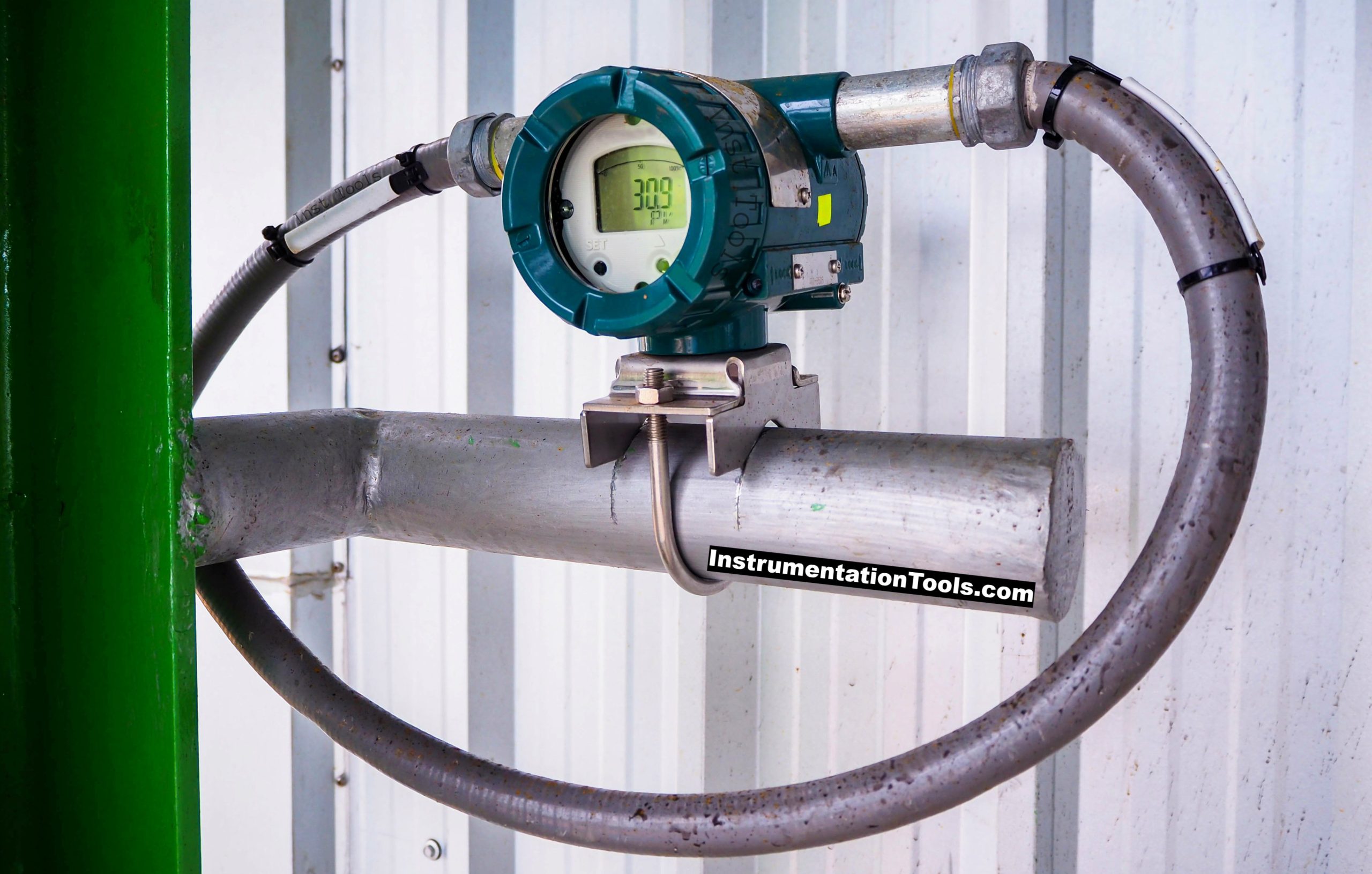
Temperature Sensors Fault

Background of the Plant Shutdown

A total of 18 temperature tags were going 0 degrees centigrade and coming back normal within a few seconds. This issue was seen frequently for the last 2 days. For the last few minutes, these tags were showing continuously 0 degrees centigrade.

So, the Operation Engineer asked the Instrumentation Engineer to check for the issue and resolve it. The instrumentation Engineer took a permit to check/replace a temperature multiplexer (MUX) which had these 18 temperature tags and started doing the job.

After 20 minutes, the other 18 temperature tags also went 0 degrees centigrade Instrumentation Engineer suddenly rushed to another temperature mux to see its status. It was working ok and no abnormality was found.

The instrumentation Engineer checked everything in that temperature mux but everything was found normal.

Plant Shutdown Analysis

Now let us try to figure out what happened and how the issue was resolved.

  1. The Operation Engineer informed the Instrumentation Engineer about the problem with the 18 temperature tags and issued a permit for checking the job.
  2. The instrumentation Engineer went to the field to check the temperature MUX as all 18 tags were in the same temperature mux and found that the mux is in power ON condition (This is area 1 temperature mux).
  3. Red LED on the temperature mux was ON which indicates fault. So, the Instrumentation Engineer tried to power reboot the temperature mux. On power reboot also, the red LED was ON which indicated that the temperature mux is faulty.
  4. The instrumentation Engineer arranged a spare temperature mux for replacement. This temperature mux was already pre-configured and was ready to be used in case of emergency.
  5. The instrumentation Engineer removed the faulty temperature mux and installed a spare temperature mux and powered it ON.
  6. After a few seconds, the Instrumentation Engineer received a contact from the Operation Engineer. The Operation Engineer said that some other 18 tags also went to 00 centigrade (This is area 2 temperature mux).
  7. Instrumentation Engineer rushed to area 2 temperature mux. On seeing the temperature mux, everything was found healthy.
  8. He tried to power reboot the area 2 temperature mux. When Instrumentation powered off the 2 temperature mux, he received contact from the operation team that all 18 temperature tag readings were coming but there was something wrong. These readings are of area 1.
  9. The Instrumentation Engineer understood everything and rushed to area 1 temperature mux and changed the Modbus address to 1 from 2.
  10. Then he went to area 2 temperature mux and powered it ON. All data became healthy.

What happened and why it was happened?

When the instrumentation Engineer arranged a spare for the temperature mux, it was installed on the test bench. A few other engineers were working on it for some reason.

At that time, they might have given it the Modbus address as 2. So, when the Instrumentation Engineer installed this temperature mux, 2 temperature mux with the same Modbus addresses were present on the system and so, PLC started showing 0 degrees centigrade for all 36 tags.

When the Instrumentation Engineer powered off the area 2 temperature mux, at that time the temperature mux in the area 1 was present online with Modbus address 2. So, all temperature tags of area 2 started showing the value of area 1. After changing the area 1 temperature mux’s Modbus address to 1, issue got resolved.

So, learning from the incident is that whenever an addressable device is there, then give it an address that does not match with already installed systems in the plant. Or write the address on the device.

If you liked this article, then please subscribe to our YouTube Channel for Instrumentation, Electrical, PLC, and SCADA video tutorials.

You can also follow us on Facebook and Twitter to receive daily updates.

Read Next:

  • Solenoid Valve Failure in Start-Up
  • Root Cause Analysis for Plant Trip
  • Malfunctioning Inlet Check Valves
  • BP Refinery Explosion at Texas City
  • Junction Box Problems and Solutions
Don't Miss Our Updates
Be the first to get exclusive content straight to your email.
We promise not to spam you. You can unsubscribe at any time.
Invalid email address
You've successfully subscribed !

Continue Reading

Effect of Lead Wire Resistance on RTD
Response Time Test of RTD and Thermocouple
Cooling Tower fan FRP fan blades saves and saves
Captive Power Plant Trip Root Cause Analysis
RTD Calculator Software
Junction Box Internal Corrosion Problems and Solutions
Share This Article
Facebook Whatsapp Whatsapp LinkedIn Copy Link
Share
Leave a Comment

Leave a Reply Cancel reply

Your email address will not be published. Required fields are marked *

Stay Connected

128.3kFollowersLike
69.1kFollowersFollow
210kSubscribersSubscribe
38kFollowersFollow

Categories

Explore More

Components of RTD
Instrument Steam Pressure Taps Primary Block Valves Glands and Bonnets Leaks
Root Cause Analysis of Differential Pressure Level Transmitter
Pressure Switch Frozen Screwed Cover Extends the Plant Shutdown
Thermocouple Construction
Fire burnt Ammonia Converter Thermocouples Problem
Radiation Pyrometer Working Principle
Cooling Tower Fans Frequently Failing

Keep Learning

Control Valve Whisper Trim Cage

Problem with Choked Control Valve with Whisper Trim Cage

Doubtful Temperature Readings

Doubtful Temperature Readings threatens Soaking Pit Wrecks 

Compressor IP Case Discharge Temperature Gradually Increases

Compressor IP Case Discharge Temperature Gradually Increases

Stability and Uniformity of Temperature Bath

Stability and Uniformity of Temperature Bath

Thermocouple Wiring Diagram

Basics of Thermocouples and RTD

Replace Failed Motors Quickly and Easily

Replace Failed Motors Quickly and Easily

field-mounted thermocouple

Thermocouple Extension Wires

Target Flow Transmitter Problem

Target Flow Transmitters Failed the Very Midnight

Learn More

instrumentation-calculator

Instrumentation Calculator

Electrical Machines Questions and Answers

MCQ on Rotating Electrical Machines

What is a Condensate Pot? How to Install it?

Compressor IP Case Discharge Temperature Gradually Increases

Compressor IP Case Discharge Temperature Gradually Increases

Digital Electronics Multiple Choice Questions

Boolean Logic Operations Objective Questions

valve trim characteristics

Control Valve Trim Characteristics

Intrinsic Safety Barriers

Intrinsically Safe Barriers Questions and Answers

How to export in Vijeo Designer

Vijeo Designer software – Import and Export

Menu

  • About
  • Privacy Policy
  • Copyright

Quick Links

  • Learn PLC
  • Helping Hand
  • Part Time Job

YouTube Subscribe

Follow US
All rights reserved. Reproduction in whole or in part without written permission is prohibited.
Welcome Back!

Sign in to your account

Username or Email Address
Password

Lost your password?