Tank gauging measurements are normally performed for one of the following reasons:
1. Operations
The main reason for this type of level measurement is to attempt to avoid unintentional overfilling or emptying of the tank during everyday operations. This form of measurement would tend to be continuous, and act as a monitor.
It is also possible for this type of application to initiate alarms.
2. Stock control
This requires a higher level of measurement accuracy than that used for operational monitoring because it is used to account for all quantities of products on site.
This type of system is used for applications such as leak detection or ensuring that onsite product quantities do not exceed those permitted. This application can operate in either continuous or periodic modes.
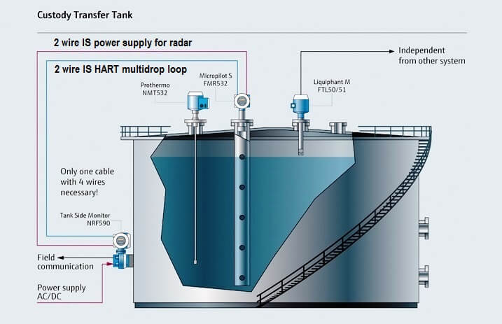
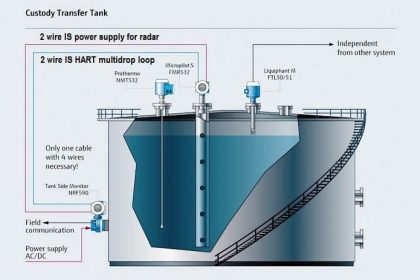
3. Custody transfer
This generally requires the highest accuracy level measurement because it is normally associated with the trading of the product. This application of tank gauging would be continuous, but only be used when a transfer was required.
Of the three applications in which tank gauging is normally applied, there are two general modes of operation;
- Periodic: Level measurement is performed after predefined intervals or under demand.
- Continuous: The level of the tank contents is always being measured by the level measurement instrumentation.
The design and required application would ultimately dictate how the particular system operates.
Uncertainties in Tank Gauging
There are numerous factors that affect the accuracy of tank level measurement.
Common uncertainties include but are not limited to:
- The positioning of the measurement system on and around the tank. For example, temperature measurement from a single sensor may not be sufficient if the tank and its contents are susceptible to temperature stratification. The positioning of a radar device may not account for the tank infrastructure;
- Position of the tank in the environment with respect to weather factors such as wind, heat and abnormal pressure;
- Tank construction should consider pressurization at the design stage.
Approvals of Systems and Components
Inspectors certify each system individually to ensure that the measurement system in place on the storage tanks is of sufficient accuracy for custody transfer. Therefore whenever maintenance is performed, recertification is necessary.
MMI (German) and PTB (Dutch) are internationally recognized standards that are used and referenced in the world of level measurement and apply to the certification weights and measurements.
The purpose of tank gauging is two-fold:
- To gauge if the contents of a storage tank are within safe limits;
- To accurately know the quantity of the product in a container for inventory and stock control.
The certified equipment is as follows.
For gasoline storage, the tank side of the level measurement system is classified as a generally hazardous area (ATEX). At the very least the electrical and instrumentation installation requires the use of ex-rated equipment.
Safety Integrity Level (SIL) ratings are not generally associated with tank level measurement equipment and are not of great significance for tank storage control systems, although relevant for Buncefield-like installations. Similarly to the process industry, SIL ratings are sometimes misquoted as referring to a component, rather than the system as a whole.
Safety systems can be approved or certified by an independent third party. Certification bodies that are commonly used in the industries include, but are not restricted to:
- TUV Rhineland;
- Exida (a popular choice);
- SIRA.
Certification of the level measurement system components demonstrates that the system has been implemented with consideration given to guidance such as Functional safety – Safety instrumented systems for the process industry sector.
Case studies
BP, Texas City
This incident happened on 23rd March 2005 at the BP Texas City refinery, Texas, USA. This incident occurred primarily because of shortcomings in the level measurement instrumentation on the Raffinate Splitter Tower. In essence, the level monitor was set up to alarm once the tower contents level reached 10 feet. Although the level monitor did alarm at this level, this event resulted in heavy hydrocarbons completely filling and overflowing the tower.
Human factors issues were also highlighted as being contributors to this incident. The details of this incident and the factors which contributed to it are beyond the scope of this report, but the Baker report, the Mogford report and the CBS report all give detailed accounts and expert opinions on this incident.2 Fifteen people died and 170 were harmed as a result of this incident.
Hertfordshire Oil Storage Terminal, Buncefield
This incident occurred on 11th December 2005 on the Hertfordshire Oil Storage Terminal near Hemel Hempstead in England. The incident was the result of a storage tank overfill that formed a dense vapor cloud which subsequently ignited and exploded. The MIIB has officially stated that the reason the overfill occurred was because the level measurement gauge on the tank did not alter in a three-hour period, despite the fact it was being continuously fed unleaded petrol via a pipeline from the Lindsey Oil Refinery in Lincolnshire.
The third progress report as presented in The Buncefield Incident 11 December 2005, The Final Report of the Major Incident Investigation Board, Volume 2, stated that findings of the investigation into the instrumentation and controls confirmed this. It emphasized that in the three-hour period prior to the incident, the level gauge of this tank remained static, despite there being a continuous transfer to it.
This loss of containment (LOC) incident was in part due to shortcomings in the control and instrumentation and in particular the failings of the tank gauging system in place on the tank that monitored the level of fuel stored in that tank. A major outcome from this investigation was the issuing of a safety notice on the type of switch used on this tank gauging system.
Read Next:
- Servo Tank Gauge Principle
- Industrial Control Systems
- System Architecture Model
- Interface for SCADA System
- Tank Gauging Technologies


Very useful information. Thank you.