Inst ToolsInst ToolsInst Tools
  • Courses
  • Automation
    • PLC
    • Control System
    • Safety System
    • Communication
    • Fire & Gas System
  • Instrumentation
    • Design
    • Pressure
    • Temperature
    • Flow
    • Level
    • Vibration
    • Analyzer
    • Control Valve
    • Switch
    • Calibration
    • Erection & Commissioning
  • Interview
    • Instrumentation
    • Electrical
    • Electronics
    • Practical
  • Q&A
    • Instrumentation
    • Control System
    • Electrical
    • Electronics
    • Analog Electronics
    • Digital Electronics
    • Power Electronics
    • Microprocessor
Search
  • Books
  • Software
  • Projects
  • Process
  • Tools
  • Basics
  • Formula
  • Power Plant
  • Root Cause Analysis
  • Electrical Basics
  • Animation
  • Standards
  • 4-20 mA Course
  • Siemens PLC Course
Reading: Something is Wrong with Strain Gauge Bridge Circuit
Share
Notification Show More
Font ResizerAa
Inst ToolsInst Tools
Font ResizerAa
  • Courses
  • Design
  • PLC
  • Interview
  • Control System
Search
  • Courses
  • Automation
    • PLC
    • Control System
    • Safety System
    • Communication
    • Fire & Gas System
  • Instrumentation
    • Design
    • Pressure
    • Temperature
    • Flow
    • Level
    • Vibration
    • Analyzer
    • Control Valve
    • Switch
    • Calibration
    • Erection & Commissioning
  • Interview
    • Instrumentation
    • Electrical
    • Electronics
    • Practical
  • Q&A
    • Instrumentation
    • Control System
    • Electrical
    • Electronics
    • Analog Electronics
    • Digital Electronics
    • Power Electronics
    • Microprocessor
Follow US
All rights reserved. Reproduction in whole or in part without written permission is prohibited.
Inst Tools > Blog > Practical Questions > Something is Wrong with Strain Gauge Bridge Circuit

Something is Wrong with Strain Gauge Bridge Circuit

Last updated: June 4, 2020 9:18 am
Editorial Staff
Practical Questions
No Comments
Share
3 Min Read
SHARE

A strain gauge is an array constructed from thin metal film designed to increase resistance as it is stretched and decrease resistance as it is compressed.

Strain gauges are typically bonded to metal specimens undergoing mechanical testing, as a means of sensing how much strain is being applied to that metal specimen.

In order to translate the resistance of the strain gauge into a measurable voltage signal, the strain gauge is typically incorporated into one arm of a “bridge” circuit.

Strain Gauge Bridge Circuit

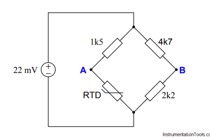
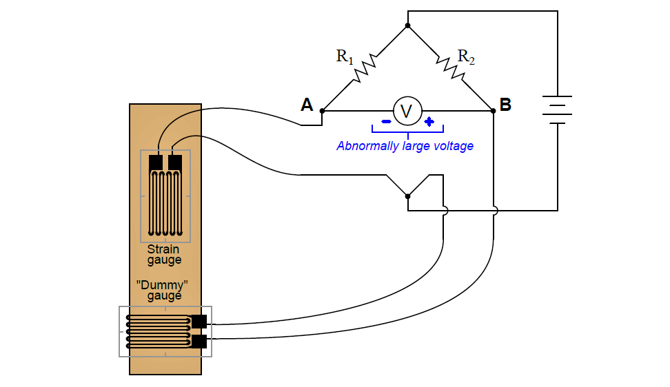
The following bridge circuit uses two strain gauges (one to measure strain, the other to compensate for temperature changes), the amount of strain indicated by the voltmeter in the center of the bridge. Unfortunately, though, it has a problem.

Instead of registering a very small voltage as it normally does, the voltmeter is “pegged” (driven beyond its normal full-range measurement) by a large voltage difference, with point B positive and point A negative as shown here:

Strain Gauge Bridge Circuit

Something is wrong in the bridge circuit, because this voltage is present even when there is no physical stress on the specimen. Identify which of the following faults could cause the excessive voltage to appear across the voltmeter, and which could not. Consider only one of these faults at a time (no multiple or simultaneous faults):

The below list shows the different types of faults. Identify which faults are possible to occur and which are not.

  • R1 failed open
  • R2 failed open
  • Strain gauge failed open
  • Dummy gauge failed open
  • R1 failed shorted
  • R2 failed shorted
  • Strain gauge failed shorted
  • Dummy gauge failed shorted
  • Voltage source dead

Answer:

  • Resistor R1 failed open – Possible
  • Resistor R1 failed shorted – Not possible
  • Resistor R2 failed open – Not possible
  • Resistor R2 failed shorted – Possible
  • Strain gauge (measurement) failed open – Not possible
  • Strain gauge (measurement) failed shorted – Possible
  • “Dummy” gauge (temperature compensation) failed open – Possible
  • “Dummy” gauge (temperature compensation) failed shorted – Not possible
  • Voltage source is dead (no voltage output at all) – Not possible

Questions For You:

1. Identify which fundamental principles of electric circuits apply to each step of your analysis of this circuit. In other words, be prepared to explain the reason(s) “why” for every step of your analysis, rather than merely describing those steps.

2. Explain why the two strain gauge elements are orthogonally bonded (i.e. attached 90o to each other) to the specimen.

Share your answers with us through below comments section.

Read Next:

  • Temperature Detectors
  • Strain Gauge Load Cell
  • Parallel Short Circuit Faults
  • Level Switch Control Logic
  • Strain Gauge Accelerometer

Credits: Tony Kuphaldt
Don't Miss Our Updates
Be the first to get exclusive content straight to your email.
We promise not to spam you. You can unsubscribe at any time.
Invalid email address
You've successfully subscribed !

Continue Reading

Draw Wiring of a Pressure Switch to control two lamps
Purpose of Stop in a Pressure Measuring Instrument
Calculate Amount of Weight Indicated by the Scale
DP transmitter Elevated 10 Feet above the Vessel
Practical Process Control System Questions & Answers – 4
Question on Remote Seal with Capillary Tubing Transmitter
Share This Article
Facebook Whatsapp Whatsapp LinkedIn Copy Link
Share
Leave a Comment

Leave a Reply Cancel reply

Your email address will not be published. Required fields are marked *

Stay Connected

128.3kFollowersLike
69.1kFollowersFollow
208kSubscribersSubscribe
38kFollowersFollow

Categories

Explore More

A Question on Density Gauge
Fisher model 546 I/P transducer
Galileo Thermometer
Questions on Dip Tube Type Level System
Smart DP Transmitter Flow Meter Calculations
Is it Possible to Measure Liquid-Liquid Level Interface using Float?
Calculate LRV and URV for 4-20 mA Loop-powered DP Transmitter
Programmable Logic Controller (PLC) Questions and Answers – 12

Keep Learning

Problem with Pirani Gauge

Problem with Pirani Gauge

Pneumatic Amplifying Relay

Determine Effect of Each Fault for Pneumatic Force-balance System

High and Low Ports on Pneumatic DP Transmitter

Identify High and Low Ports on Pneumatic DP Transmitter

Steam Eductor Question

A Series of False Pressure Alarms

Calculate Temperature of Four Wire RTD

Calculate the Temperature of 4 Wire RTD

Calculate Hydraulic Pressure of a Drum

Calculate Hydraulic Pressure of a Process Vessel

Calculate the Magnitude of Hydrostatic Pressure

Calculate the Magnitude of Hydrostatic Pressure

DP Transmitter Located 10 feet Beneath the Vessel

DP Transmitter Located 10 feet Beneath the Vessel

Learn More

Material Take Off (MTO)

What is Material Take Off (MTO)? – Purpose, Components, Uses

Instrumentation Symbols Legend

Instrumentation Symbols Legend

PM of Instrument Air Compressor

PM of Instrument Air Compressor in Oil & Gas Plants

Electrical Machines Questions and Answers

Induction Motor Rotor EMF, Current and Power

Analog Measurement using Ladder Logic

Analog Measurement using Ladder Logic

Top 100 Switchgear and Protection Interview Questions

Top 100 Switchgear and Protection Interview Questions

Alarm Trip for 24v DC Loop

Advantages & Disadvantages of Synchronous Motors

Career Scope in Electronics Engineering

Career Scope in Electronics Engineering

Follow US
All rights reserved. Reproduction in whole or in part without written permission is prohibited.
Welcome Back!

Sign in to your account

Username or Email Address
Password

Lost your password?