In this article, you will learn the main steam pressure control, liquid fuel pressure, fuel gas and combustion air pressure, and furnace draft.
Steam Pressure Control
Drum pressure indicates the heat balance between the inflow and outflow of a boiler.
A balance between steam demands depends on plant load and steam supply from all boilers the power station can be established by controlling the common bus pressure.
A variation in the pressure of the main steam is awaited after a delay of a few minutes from a change in firing rate and is based on the boiler condition and the load level.
A feed-forward control improves pressure control by adjusting fuel as a change in load is observed, instead of waiting for pressure to change first.
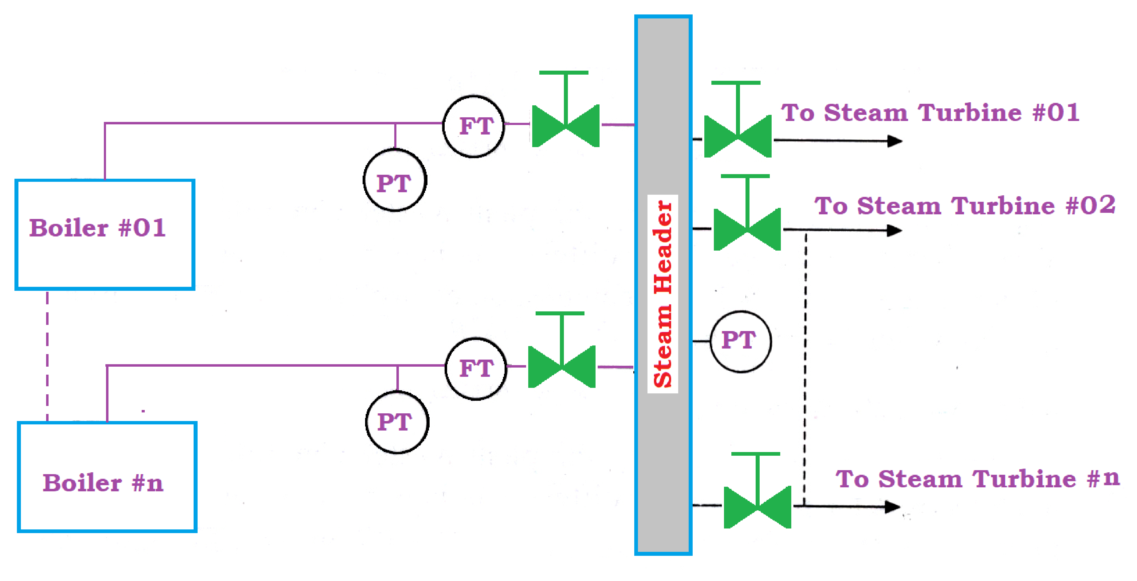
In all thermal power stations having more boilers and steam turbines, a common steam bus or steam header is used to circulate steam from all boilers to all steam turbines.
The net steam generation and consumption are equal at the balanced condition when temperature and pressure are controlled.
An automatic pressure control system is required to meet the load fluctuations for the steam consumed from the common steam header hence the pressure varies.
The pressure can be varied only by adjusting the firing rate of the furnace in the boilers.
The controller output is shared among the number of boilers.
The proportion of sharing among boilers depends on the boiler condition.
The below figure shows the steam supply system with an ‘N’ number of boilers with equal steam turbines.
The steam header pressure uses a master pressure signal to decide the firing rate demand among various boilers.
Feedback Steam Pressure Control
If one to one combination like one steam turbine for one boiler is followed, then the process parameters used to set fuel demand, the firing rate of the boiler, or combustion control is of steam pressure or steam flow.
Having more boilers installed to supply steam to the common header in parallel, is desired to adjust the load distribution among these boilers.
It is successfully achieved by feedback control of header pressure.
Based on the main steam load and the performance of the individual boilers, an efficient operation is performed with some boilers by keeping them shut down, some boilers with constant firing rate, and the remaining boilers swing with the load called variable firing rate.
The feedback plant master control generates net fuel demand and firing rate demand by considering steam header pressure as the input and controlled variable.
The net fuel demand is distributed among various boilers is discussed above.
Each boiler master consists of its own bias adjustment and an auto/manual transfer switch.
In manual mode, the boiler operator reduces the firing rate to a minimum firing condition to shut down the boiler, or holds the firing rate at appropriate load conditions.
But, in auto mode, the boiler master follows the master firing rate demand signal except as modified by the bias adjustment.
The operator can adjust the boiler master bias up to increase or down to reduce the load.
The plant master controller through boiler master controllers generates firing rate demand for various boilers and becomes the set point for combustion controllers of concerned boilers.
Feed Forward + Feedback Steam Pressure Control
The net main steam flow from the boiler is used as a feed-forward signal to get a faster reply from the master controller for firing rate demand for the individual boilers.
Practically, it is not possible to measure the main steam flow inlet or outlet from the steam header by the individual flow meter.
The generated main steam from individual boilers or the steam consumed by individual steam turbines is mixed together.
An arrangement of feed forward-plus-feedback master control is shown in Figure below.
In this arrangement, the total net main steam flow from all boilers is considered as feed-forward demand.
The proportional multiplier function is adjusted at the input side of summer such that a change in the main steam flow produces an accurate steady-state change in firing rate demand.
The steam pressure controller provides the correct adjustment of the firing rate demand for over-firing or under-firing to adjust energy input.
In the normal power plant installation, variation in steam header pressure is due to the change in steam flow rate demand at the receiver side of the steam header.
If there is a high-pressure drop between the boiler and steam header, then the change in steam flow rate causes a large change in steam header pressure due to changes in supply-side pressure drop.
These pressure changes define different things in the system.
The change in steam pressure demand at the receiver side symbols for change in firing rate should be changed because the user requires maximum steam.
A change in steam pressure drop on the supply side indicates a change in the firing rate to change the stored energy represented by boiler pressure is required.
Main Steam and Liquid Fuel Pressure
The pressure of liquid fuel and atomized steam pressure is measured by pressure transmitters. But for local indication, bourdon gauges are used.
An electronic transmitter either a strain gauge or capacitance type is used to transmit the measured signal from the field to the control room.
The pressure range may vary from 0 to 20 bars.
The temperature of the measuring liquid fuel in signal pipelines must be maintained because the oil may get solidified during pressure measurement.
Fuel Gas and Combustion Air Pressure
The pressure of fuel gas and combustion air must be in the order of 0 to 2000 mmwc.
For local indication and signal transmission of the pressure signal membrane type or capsule, type sensors are.
The following are some of the sensing points.
Fuel gas main line pressure
Pressure before and after the pressure control valve (PCV)
FD fan outlet pressure
Pressure before and after air preheater
The pressure prior to the burner
Flue Gas and Waste Gas Pressure
Flue gas pressure ranges between 50 mmwc to -100 mmwc while traveling from the combustion chamber to the atmosphere through an economizer, air preheater, electrostatic precipitator ID fan, and chimney.
The positive pressure is generated by combustion air pressure and gas pressure at the entering point.
The negative pressure is generated by the ID fan and chimney for the flue gas to flow out to the atmosphere. Differential pressure sensors with a diaphragm or membrane are employed utilized to measure such low pressures.
Both direct reading and transmission types are possible.
The various measuring locations of the flue gas are listed below:
Combustion chamber pressure
Pressure before and after the economizer
Pressure before and after air preheater
Pressure before and after ID fan
Pressure before the chimney.
Furnace Draft
Basically, combustion air and fuel flow into the combustion chamber of the furnace, and flue gas flows outside.
The force driving this flow is DP between the gases inside the furnace and those outside the furnace.
Furnace pressure is generally known as draft or draft pressure.
The draft pressure is maintained slightly negative to prevent the combustion products and ash from being discharged from the furnace into surrounding areas through inspection ports, doors, feeders, etc.
The range of the furnace pressure is about ± 20 mmwc.
The location of the furnace pressure tapping is very essential to obtain a representative sample.
The choice of pressure tap locations for measuring the furnace draft is shown in the figure below.
The pressure connection on boilers is located on the front (1), side (2), or roof (3) of the furnace
The pressure measurements at these three locations are for the same furnace chamber of a particular boiler.
The measurement values may vary depending on differing stack or chimney effects.
Pressure measurement in the roof of the furnace mark for maximum value. But it is essential to have negative pressure at all points.
The measured pressure value at the furnace roof becomes the controlling factor in determining the desired set point.
Sorry, But I can't agree with the concept of Boiler Load Sharing based entirely on Range & Individual Steam Pressure.
The philosophy I developed and proved many times in Sugar Industry Boilers is based on a Range Pressure Master controller, manipulating the firing rate demand of each Boiler, forcing it to deliver the FLOW and not the pressure ( which is constant in the header).
Load changes in any factory are 'Wild' and it is this change in flow demand which is the first parameter to change, NOT the header Pressure. If you want to read my white paper on the subject, please contact me. I am currently redesigning a complete factory steam supply reticulation system for a one of the largest factories in Africa and am prepared to share my concept and design.
Hello Charles, could you please share with me the mentioned white paper


View Comments
Sorry, But I can't agree with the concept of Boiler Load Sharing based entirely on Range & Individual Steam Pressure.
The philosophy I developed and proved many times in Sugar Industry Boilers is based on a Range Pressure Master controller, manipulating the firing rate demand of each Boiler, forcing it to deliver the FLOW and not the pressure ( which is constant in the header).
Load changes in any factory are 'Wild' and it is this change in flow demand which is the first parameter to change, NOT the header Pressure. If you want to read my white paper on the subject, please contact me. I am currently redesigning a complete factory steam supply reticulation system for a one of the largest factories in Africa and am prepared to share my concept and design.
Hello Charles, could you please share with me the mentioned white paper