Root Cause Analysis (RCA): Steam turbine (K-601 T) 100-40 bar steam letdown station 3-year long persistent flange leaks stopped.
| Article Type: | Root Cause Analysis (RCA) |
| Category: | Mechanical |
| Equipment Type: | Pipelines and Miscellaneous Problems |
| Author: | S. Raghava Chari |
Note: This root cause analysis (RCA) is from real-time scenarios that happened in industries during the tenure of two or three decades ago. These articles will help you to improve your troubleshooting skills and knowledge.
Background Information
1500 T/d NH3 plants 2 Nos. fired boilers start first. Each feed 100 T/H 40 bar superheated steam (SHS) into the 40‑bars SHS header. The frontend plants start using this SHS.
They stabilize in two days and deliver Synthesis gas (SG 75% H2 and 25% N2 gas mixture) and their waste heat boilers around 360 T/H 100-bars 530o C SHS. The plant vents the SG till the required purity is achieved and letdown the 100-bars SHS.
into the 40-bars SHS header. The plant DCS adjust the firing to hold the 40‑bars SHS pressure constant.
K-601 starts compressing the pure SG and venting stops. Its drive turbine K‑601 T admits the entire 360 T/H 100-bar SHS. 330 T/H extracted SHS from it joins the 40-bar SHS header. K-601 T condenser condenses the balance 30T/H SHS.
As before the DCS adjusts firing to hold the 40‑bar SHS pressure constant. Thus, the letdown station avoids wasteful SHS venting and noise pollution during the two after front end start and stabilizing days.
The paragraph letdown station’s configuration describes its other benefits.
Letdown Station Description
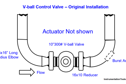
Vertically downwards 10” pipe tap off from 100 bar SHS header branches into 3 Nos. zero elevation floor supported 6” pipe branches.
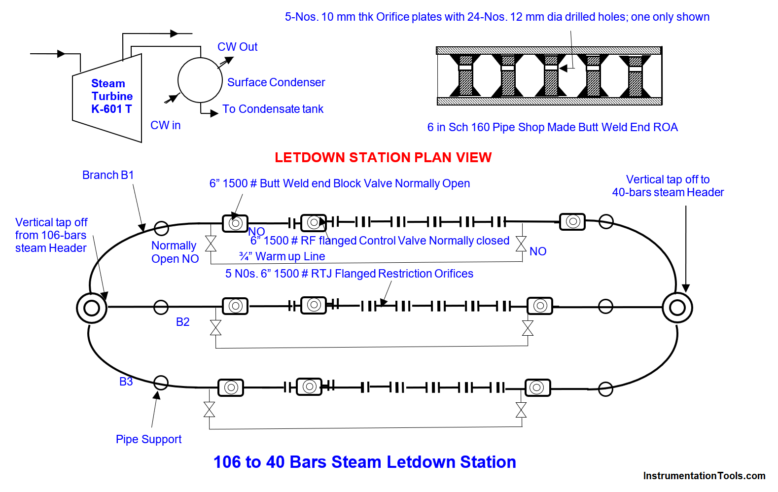
The branches combine into a 10” vertical takeoff joining the 40‑bar SHS header (fig 1). Each branch consists of:
- 6” both ends welded inlet block valve
- 6” 1500 # RTJ flanged control valve (CV)
- CV downstream 5 Nos. 8” 1500 # RTJ flanged restriction orifice assemblies (ROA). The 5 ROAs absorb around 80% letdown pressure for the below given reasons:
- Enables selecting line size control valve for high pipeline strength
- The low across CV ▲P minimizes valve plug and seat erosion and prolongs their lives
- ROA downstream 6” 1500# butt weld end block valve
- Connecting piping and pipe supports
Letdown Station Configuration
Below is the system configuration:
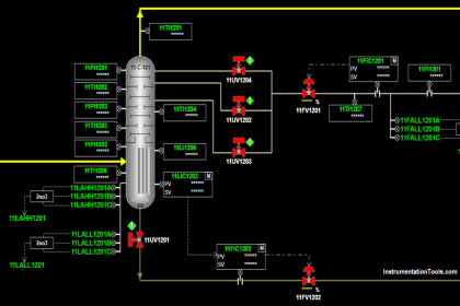
- One Manual Station outputs 70% (15.2 mA) open signal to Branch 1 (B1) letdown CV. This signal passes via K-601 T Trip Throttle Valve (TTV) close limit switch (LS)
- On K-601 T trip the LS conveys the 15.2 mA B 1 CV; it opens 80% within 3 secs, lets down bulk of the K‑601 T consumed steam into the 40-bars steam header.
- The DCS controls the 100-bars header pressure by operating B2 and B3 CVs in split range control and also the 40-bars SHS header pressure by adjusting the boilers firing
- Thus, the letdown system controls the 40-bar and 106-bar steam pressures rapidly to prevent safety valves blowing and for continued waste heat boiler runs
The above mentioned are letdown stations other benefits referred previously.
Steam Letdown Station Problems
from day-1 estimated 20 T/H 1 huge SHS leaks wasted enormous money. Repeated ring gasket changes at available plant shutdown (SD) opportunities, online hot bolting, and online leak sealing were futile.
The author replaced the flanged ROs with shop pre-made butt weld end Restriction Orifice Assemblies eliminated 15 flange joints and their leaks. However, leaks to a much smaller extent developed at the three Nos. CV flanges.
The author rejected his colleagues’ insistence to weld the control valves also to the pipelines, as he now became certain that pipeline stresses warping the flanges is the unstoppable flange leaks’ root cause.
Welding the CVs also to the pipe removes the only stress relief point; hence, the pipe could burst and the resulting huge quantities of steam spills would be unmanageable and shutdown the plant for several days. The only benefit was former leaks 20 % only now, which paid the welded orifice assembly installation costs in a week.
Constant thinking and several site studies finally revealed to the author the flange leaks Root Cause viz. the piping stresses elimination:
He concluded pipe supports welded to the pipes at the top and their foot plates grouted to concrete floor prevented the pipes’ temperature change travels i.e. zero pipeline flexibility to put in pipe designers’ parlance – the root cause. Remember 530o C steam flows through the pipe!
Below listed the author got done online piping flexibility improving remedies stopped the 3-yearlong solution defying steam leaks.
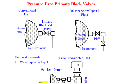
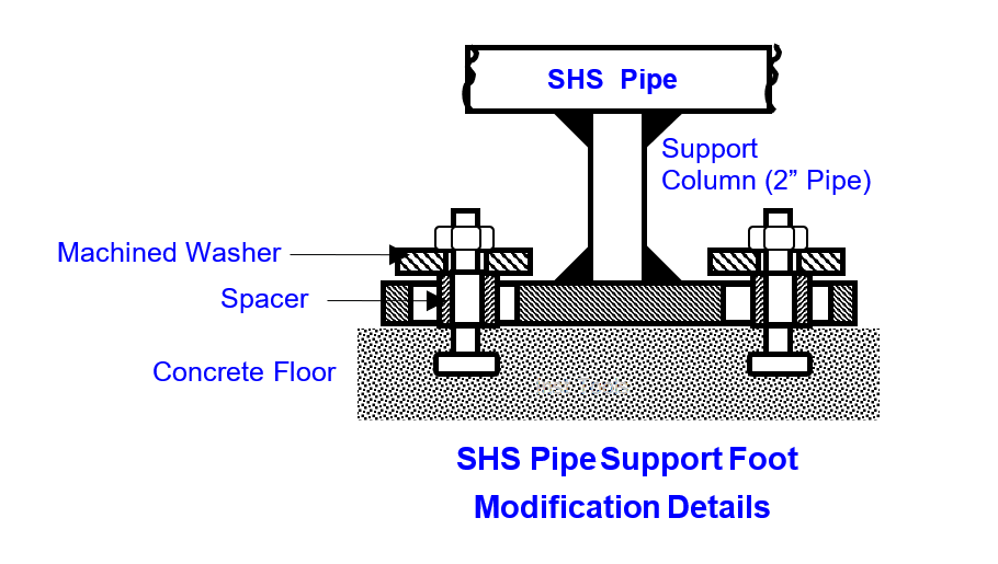
- Crew flame cut the support foot plate bolt holes oblong along pipe travel direction i.e. along pipe length (fig 2)
- They inserted shop made spacers (S) on the bolts protruding 1‑mm above foot plate
- The foot plate to ground securing nuts bottom on the spacers; this way B1, B2, B3 travel freely with temp changes dragging their supports sliding on the floor
- I.e. B1, B2 & B3 have enough thermal travel flexibilities.
Benefits of the RCA based solution
Below listed are the realized benefits:
- The three yearlong flange leaks vanished as if magic confirming the diagnosis and effectiveness of the solution
- Estimated 20 T/H flanged orifice assembly leaks during the first year and 1 T/H control valves flange leaks during the subsequent 2 years and its enormous costs vanished
Stopping the leaks by eliminating the high stresses due to flexibility lack eliminated the previously described sudden unexpected potential pipe ruptures, associated catastrophes and long plant outage.
Author: S. Raghava Chari
Do you face any similar issues? Share with us through the below comments section.
If you liked this article, then please subscribe to our YouTube Channel for Instrumentation, Electrical, PLC, and SCADA video tutorials.
You can also follow us on Facebook and Twitter to receive daily updates.
Read Next:
- Leaking Plug Valves
- Flange Joint Problems
- Pipe Elbow Sudden Burst
- Fan Motor Journal Bearing Failures
- Fired Boiler Induced Draft Fan Failures