Inst ToolsInst ToolsInst Tools
  • Courses
  • Videos
  • Q & A
    • Interview
      • Instrumentation
      • Electronics
      • Electrical
      • Practical Questions
    • MCQ
      • Instrumentation MCQ
      • Electrical MCQ
      • Electronics MCQ
      • Control Systems MCQ
      • Analog Electronics MCQ
      • Digital Electronics MCQ
      • Power Electronics MCQ
      • Microprocessor MCQ
      • Multiple Choice Questions
  • EE
    • Electronics
      • Electronics Q & A
      • Electronic Basics
      • Electronic Devices & Circuits
      • Electronics Animation
      • Digital Electronics
    • Electrical
      • Electrical Basics
      • Electrical Q & A
      • Power Electronics
      • Electrical Machines
      • Electrical Animation
      • Power Systems
      • Switchgear & Protection
      • Transmission & Distribution
  • Measure
    • Control Valves
    • Calibration
    • Temperature
    • Pressure
    • Flow
    • Level
    • Analyzers
    • Switches
    • Vibration
    • Solenoid Valve
  • Control
    • PLC Tutorials
    • Control Systems
    • Safety Instrumented System (SIS)
    • Communication
    • Fire & Gas System
  • More
    • Design
    • Tools
    • Animation
    • Basics
    • Formulas
    • Standards
    • TextBooks
    • Common
    • Software
    • Excel Tools
    • Erection & Commissioning
    • Process Fundamentals
    • Videos
    • Books
Search
All rights reserved. Reproduction in whole or in part without written permission is prohibited.
Reading: Starting a Synchronous Motor
Share
Notification Show More
Font ResizerAa
Inst ToolsInst Tools
Font ResizerAa
  • Courses
  • PLC Tutorials
  • Control Systems
Search
  • Courses
  • Videos
  • Q & A
    • Interview
    • MCQ
  • EE
    • Electronics
    • Electrical
  • Measure
    • Control Valves
    • Calibration
    • Temperature
    • Pressure
    • Flow
    • Level
    • Analyzers
    • Switches
    • Vibration
    • Solenoid Valve
  • Control
    • PLC Tutorials
    • Control Systems
    • Safety Instrumented System (SIS)
    • Communication
    • Fire & Gas System
  • More
    • Design
    • Tools
    • Animation
    • Basics
    • Formulas
    • Standards
    • TextBooks
    • Common
    • Software
    • Excel Tools
    • Erection & Commissioning
    • Process Fundamentals
    • Videos
    • Books
Follow US
All rights reserved. Reproduction in whole or in part without written permission is prohibited.
Inst Tools > Blog > Electrical Theory > Starting a Synchronous Motor

Starting a Synchronous Motor

Last updated: August 6, 2018 9:42 pm
Editorial Staff
Electrical Theory
No Comments
Share
3 Min Read
SHARE

A synchronous motor may be started by a DC motor on a common shaft. When the motor is brought to synchronous speed, AC current is applied to the stator windings. The DC motor now acts as a DC generator and supplies DC field excitation to the rotor of the synchronous motor. The load may now be placed on the synchronous motor.

Synchronous motors are more often started by means of a squirrel-cage winding embedded in the face of the rotor poles. The motor is then started as an induction motor and brought to ~95% of synchronous speed, at which time direct current is applied, and the motor begins to pull into synchronism. The torque required to pull the motor into synchronism is called the pull-in torque.

As we already know, the synchronous motor rotor is locked into step with the rotating magnetic field and must continue to operate at synchronous speed for all loads. During no-load conditions, the center lines of a pole of the rotating magnetic field and the DC field pole coincide (Figure 1a). As load is applied to the motor, there is a backward shift of the rotor pole, relative to the stator pole (Figure 1b). There is no change in speed. The angle between the rotor and stator poles is called the torque angle (α).

Starting a Synchronous Motor

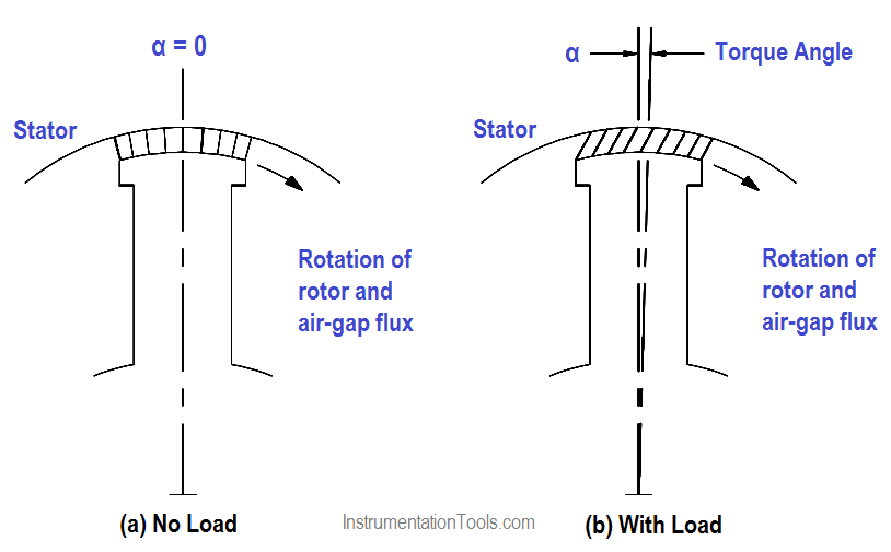
Figure 1 : Torque Angle

If the mechanical load on the motor is increased to the point where the rotor is pulled out of synchronism (α≅90°), the motor will stop. The maximum value of torque that a motor can develop without losing synchronism is called its pull-out torque.

Field Excitation

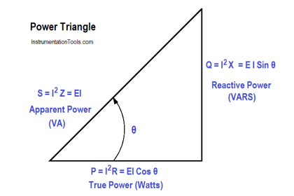
For a constant load, the power factor of a synchronous motor can be varied from a leading value to a lagging value by adjusting the DC field excitation (Figure 2). Field excitation can be adjusted so that PF = 1 (Figure 2a). With a constant load on the motor, when the field excitation is increased, the counter EMF (VG) increases. The result is a change in phase between stator current (I) and terminal voltage (VG), so that the motor operates at a leading power factor (Figure 2b).

Synchronous Motor Field Excitation

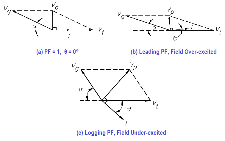
Figure 2 : Synchronous Motor Field Excitation

VP in Figure 2 is the voltage drop in the stator winding’s due to the impedance of the windings and is 90° out of phase with the stator current. If we reduce field excitation, the motor will operate at a lagging power factor (Figure 2c). Note that torque angle, α, also varies as field excitation is adjusted to change power factor.

Synchronous motors are used to accommodate large loads and to improve the power factor of transformers in large industrial complexes.

Don't Miss Our Updates
Be the first to get exclusive content straight to your email.
We promise not to spam you. You can unsubscribe at any time.
Invalid email address
You've successfully subscribed !

Recommended Articles

Parallel Circuit Current Calculations
Batteries
Transformer Voltage Ratio
AC Generation
DC Motor Speed
Calculate Power in Series RC Circuit
Share This Article
Facebook Whatsapp Whatsapp LinkedIn Copy Link
Share
Leave a Comment

Leave a Reply Cancel reply

Your email address will not be published. Required fields are marked *

Stay Connected

128.3kFollowersLike
69.1kFollowersFollow
208kSubscribersSubscribe
38kFollowersFollow

Categories

Recent Comments

  • William Snyder on Top Non-PLC Certification Courses for Automation Professionals
  • Kamli on Top Free PLC Software
  • Guifty Shimica on Top Non-PLC Certification Courses for Automation Professionals
  • Guifty Shimica on Top Non-PLC Certification Courses for Automation Professionals

Related Articles

Forward Bias

Rectifiers, Forward Bias and Reverse Bias

Gang Switch Principle

Reading Electrical Schematics

Inductor Principle

Inductor

Calculate Power in Parallel RCL Circuit

Calculate Power in Parallel RCL Circuit

Series Circuit

Series Circuit

Electric Short Circuit

Series Short Circuit Faults

Types of Batteries

Types of Batteries

Measuring Circuit Voltage

Voltmeters

More Articles

PLC Program Backup in Siemens Tia Portal

How to Take Program Backup from Physical PLC? – Siemens PLC

Time Response Analysis

State Variable Analysis – Part I

electric valve actuator

Electrical Actuators

Field Transmitter Damping

What is Field Transmitter Damping ?

Vortex Flow GIF

Working Principle of Vortex Flow Meter

Siemens PLC Organization Blocks used For Troubleshooting

Tia Portal – OB121 Programming Errors Interrupt Organization Block

Feedback Characteristics of Control Systems

Feedback and Non-feedback Systems Objective Questions

What is an Orifice Flange ?

What is an Orifice Flange? – Purpose and Applications

Follow US
All rights reserved. Reproduction in whole or in part without written permission is prohibited.
Welcome Back!

Sign in to your account

Username or Email Address
Password

Lost your password?