Inst ToolsInst ToolsInst Tools
  • Courses
  • Automation
    • PLC
    • Control System
    • Safety System
    • Communication
    • Fire & Gas System
  • Instrumentation
    • Design
    • Pressure
    • Temperature
    • Flow
    • Level
    • Vibration
    • Analyzer
    • Control Valve
    • Switch
    • Calibration
    • Erection & Commissioning
  • Interview
    • Instrumentation
    • Electrical
    • Electronics
    • Practical
  • Q&A
    • Instrumentation
    • Control System
    • Electrical
    • Electronics
    • Analog Electronics
    • Digital Electronics
    • Power Electronics
    • Microprocessor
  • Request
Search
  • Books
  • Software
  • Projects
  • Process
  • Tools
  • Basics
  • Formula
  • Power Plant
  • Root Cause Analysis
  • Electrical Basics
  • Animation
  • Standards
  • 4-20 mA Course
  • Siemens PLC Course
Reading: Overview of Split Range Control
Share
Font ResizerAa
Inst ToolsInst Tools
Font ResizerAa
  • Courses
  • Design
  • PLC
  • Interview
  • Control System
Search
  • Courses
  • Automation
    • PLC
    • Control System
    • Safety System
    • Communication
    • Fire & Gas System
  • Instrumentation
    • Design
    • Pressure
    • Temperature
    • Flow
    • Level
    • Vibration
    • Analyzer
    • Control Valve
    • Switch
    • Calibration
    • Erection & Commissioning
  • Interview
    • Instrumentation
    • Electrical
    • Electronics
    • Practical
  • Q&A
    • Instrumentation
    • Control System
    • Electrical
    • Electronics
    • Analog Electronics
    • Digital Electronics
    • Power Electronics
    • Microprocessor
  • Request
Follow US
All rights reserved. Reproduction in whole or in part without written permission is prohibited.
Inst Tools > Blog > Control Systems > Overview of Split Range Control

Overview of Split Range Control

Last updated: March 18, 2019 12:21 pm
Editorial Staff
Control Systems
5 Comments
Share
4 Min Read
SHARE

A very common control scheme is split range control in which the output of a controller is split to two or more control valves.

Split Range Control

For example:

  • Controller output 0%             Valve A is fully open and Valve B fully closed.
  • Controller output 25%           Valve A is 75% open and Valve B 25% open.
  • Controller output 50%           Both valves are 50% open.
  • Controller output 75%           Valve A is 25% open and Valve B 75% open.
  • Controller output 100%         Valve A is fully closed and Valve B fully open.

Different arrangements are possible. For example, figure 1 shows a split range pressure controller on a separator with two valves, one to the flare and one to the compressor suction. In this case, the ‘split’ is configured as follows:

  • Controller output 0%             Both valves are closed.
  • Controller output 25%           Valve A is 50% open and Valve B still closed.
  • Controller output 50%           Valve A is fully open and Valve B closed.
  • Controller output 75%           Valve A is fully open and Valve B 50% open.
  • Controller output 100%         Both valves are fully open.

The idea is that the suction valve is used for normal pressure control while the flare valve only opens to disperse high pressures.

Split range control scheme

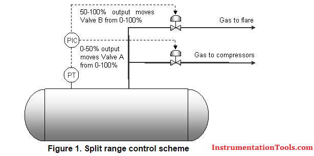
In this application, the flare valve will need to open quickly in response to high pressures, but the compressor suction valve will need to move much more slowly to prevent instability in the compressors.

The main problem with split range control is that the controller only has one set of tuning parameters. If the controller is tuned to be fast acting to optimize the performance of the flare valve, the suction valve will also move rapidly to produce unstable gas flows to the compressors.

If the controller is tuned slower to stabilize the compressors, then the flare valve will not open fast enough as the pressure rises. A further issue is that the process response of the route to flare generally differs to the process response of the route to the compressors, so both routes will anyway require very different tuning for optimal control.

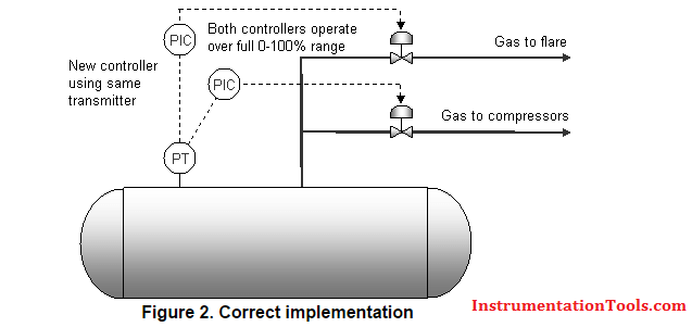
The solution is to replace the split range controller with two independent controllers, both reading the same pressure transmitter, but one controlling the flare valve and the other the suction valve.

Not only can each controller be tuned correctly for its dedicated service, but different setpoints can also be used to prevent the flare valve from ‘popping’ unnecessarily.

Split Controller

The ease with which a split range controller can be replaced with two ordinary controllers depends on a number of factors. If the ‘split’ is calculated in the DCS or PLC so that each valve has its own output from the control system, then the addition of a new controller is simply a matter of software configuration.

However, occasionally, the control system only has one output wired to both controllers and the ‘split’ produced by configuration of the valve positioner. A new output will then be required from the control system to one of the valves and the valve positioners must be reconfigured to operate over the full 0-100% output range.

Also Read: Use of Diode Protection Module

Don't Miss Our Updates
Be the first to get exclusive content straight to your email.
We promise not to spam you. You can unsubscribe at any time.
Invalid email address
You've successfully subscribed !

Continue Reading

Inspection and Testing of Fiber Optic Cable
What are AI, AO, DI, and DO? – Definition, Examples, Purpose
What is a Signal Isolator? Principle, Advantages, Disadvantages
Waste Water Control System
What is Nest Loading? – DCS and PLC Control Systems
What is a Annunciator Panel?
Share This Article
Facebook Whatsapp Whatsapp LinkedIn Copy Link
Share
5 Comments
  • Alex says:
    March 26, 2016 at 2:51 pm

    This is an excellent article which has given me an good explanation. Thanks

    Reply
  • MK says:
    October 17, 2017 at 9:58 pm

    MANY THANX

    Reply
  • ahmed.shatat says:
    November 29, 2018 at 12:36 am

    Good knowledge and more effective for all concerned person

    Reply
  • Mayamona says:
    November 7, 2020 at 7:23 pm

    Very good lecture information and technical concept of instrumentation. I feel proud of the team because as Instrument Technician we play a very important role in maintain /control/ troubleshoot the processing plants.

    Reply
  • Vidyasagar says:
    January 21, 2021 at 10:16 am

    all topics in instrumentation tools.com is very useful for instrumentation engineering students.

    thank you

    Reply

Leave a Reply Cancel reply

Your email address will not be published. Required fields are marked *

Stay Connected

128.3kFollowersLike
69.1kFollowersFollow
210kSubscribersSubscribe
38kFollowersFollow

Categories

Explore More

What is Energy Monitoring System ?
Determine Voltage Drops at Respective Flow Rates in Loop Diagram
Cascade Temperature Control System
ICS Control System Security
Liquid Level Control using Flow Loop
What is the BACNet Protocol? BACNet IP vs. BACNet MS/TP
Identify Process Variables in P&ID
Heat Exchanger Temperature Control

Keep Learning

HMI

Learn about SCADA and HMI Systems

Quantitative PID tuning procedures

Quantitative PID tuning procedures

Why Grounding

Basics of Grounding

Definitions of Electrical Grounding

Definitions of Electrical Grounding

Manufacturing Execution System in Industrial Automation

Manufacturing Execution System (MES) in Industrial Automation

Industrial Automation Systems

Remote Functions in Industrial Control Systems (ICS)

Certified Control Systems Technician (CCST) Sample Questions

Certified Control Systems Technician (CCST) Questions

PV Tracking in PID Controllers

What is PV Tracking ?

Learn More

Pros and Cons of Online Educational Services

Pros and Cons of Online Courses

direct and reverse acting PID controller Tuning

Recognizing an Over-Tuned PID Controller by Phase Shift

Difference Between Cyclic and Acyclic Communication

Difference Between Cyclic and Acyclic Communication

Chemical Battery

Batteries

PLC Program for Fish Feeding System

PLC Program for Fish Feeding System

Types-of-diodes

Different Types of Diodes

Cutaway View of Circuit Breaker

Low Voltage Air Circuit Breaker Principle

Contact-Type-GWR-Level-Transmitter-Working-Animation

Probe Type GWR Level Transmitter Working Animation

Menu

  • About
  • Privacy Policy
  • Copyright

Quick Links

  • Learn PLC
  • Helping Hand
  • Part Time Job

YouTube Subscribe

Follow US
All rights reserved. Reproduction in whole or in part without written permission is prohibited.
Welcome Back!

Sign in to your account

Username or Email Address
Password

Lost your password?