Inst ToolsInst ToolsInst Tools
  • Courses
  • Automation
    • PLC
    • Control System
    • Safety System
    • Communication
    • Fire & Gas System
  • Instrumentation
    • Design
    • Pressure
    • Temperature
    • Flow
    • Level
    • Vibration
    • Analyzer
    • Control Valve
    • Switch
    • Calibration
    • Erection & Commissioning
  • Interview
    • Instrumentation
    • Electrical
    • Electronics
    • Practical
  • Q&A
    • Instrumentation
    • Control System
    • Electrical
    • Electronics
    • Analog Electronics
    • Digital Electronics
    • Power Electronics
    • Microprocessor
Search
  • Books
  • Software
  • Projects
  • Process
  • Tools
  • Basics
  • Formula
  • Power Plant
  • Root Cause Analysis
  • Electrical Basics
  • Animation
  • Standards
  • 4-20 mA Course
  • Siemens PLC Course
Reading: SIS Software Simulation – Safety Instrumented System
Share
Notification Show More
Font ResizerAa
Inst ToolsInst Tools
Font ResizerAa
  • Courses
  • Design
  • PLC
  • Interview
  • Control System
Search
  • Courses
  • Automation
    • PLC
    • Control System
    • Safety System
    • Communication
    • Fire & Gas System
  • Instrumentation
    • Design
    • Pressure
    • Temperature
    • Flow
    • Level
    • Vibration
    • Analyzer
    • Control Valve
    • Switch
    • Calibration
    • Erection & Commissioning
  • Interview
    • Instrumentation
    • Electrical
    • Electronics
    • Practical
  • Q&A
    • Instrumentation
    • Control System
    • Electrical
    • Electronics
    • Analog Electronics
    • Digital Electronics
    • Power Electronics
    • Microprocessor
Follow US
All rights reserved. Reproduction in whole or in part without written permission is prohibited.
Inst Tools > Blog > Safety Instrumented System (SIS) > SIS Software Simulation – Safety Instrumented System

SIS Software Simulation – Safety Instrumented System

Safety Instrumented System (SIS) software simulation before commissioning of any SIF is necessary to do testing in a safety PLC.

Last updated: May 25, 2022 3:15 pm
Editorial Staff
Safety Instrumented System (SIS)
No Comments
Share
5 Min Read
SHARE

Safety Instrumented System (SIS) software simulation before commissioning of any SIF is important and also necessary to do simulation testing as and when there are changes in the safety instrumented function.

Contents
SIS Software TestsSafety Instrumented System Simulation ProgramSIS Software Simulation TestsSIS Software Documentation

Below are the brief tests followed:

  • Software program Verification
  • The SIL program shall be verified against its specification prior to initial operation by all the below:
  • Application program to be verified
  • Application program to be validated by functional tests.

SIS Software Tests

Software tests objectives shall confirm – To verify the application program works & No outside interference from other programs exists.

Parts of Safety PLC
Example: Pressure transmitters with voting 1oo2 logic. Image Courtesy: Endress Hauser

Safety Instrumented System Simulation Program

  • Items to be checked for Inputs:
    • All inputs shall not violate physical limits or boundaries
    • All inputs should produce approximately correct values
    • All inputs should reflect dynamic behavior where required
    • Test program to be created to ensure each module is checked.
    • Untested modules, modified modules, or special software program needs to be thoroughly tested to ensure they have correct interactions & communications with other modules.

Software simulation checks shall include below minimum checks:

  1. Startup and shutdown.
  2. Normal operating behavior.
  3. Alarm conditions.
  4. Safe state when required

SIS Software Simulation Tests

Software simulation tests may be done in different stages of the project (Such as integration tests with DCS vendor and Factory Acceptance Test, or field Validation tests) to show that the application software achieved its requirements on the specified hardware and within the defined time as per safety requirements.

Below parameters needs to be ensured during the SIF requirement software simulation check.

  • SIS trip at the proper setpoint
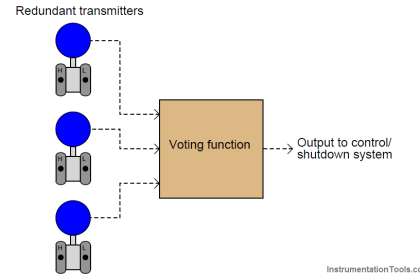
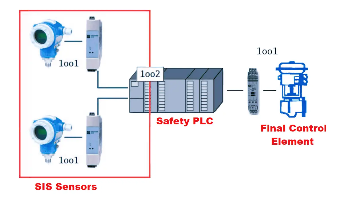
  • Configuration permutations – for 2oo3, verify with multiple 2 sensors combinations.
  • Verify the timing of the whole loop – from sensing the problem to the final action completed – conforms with the SIS loop response time as defined in the Safety Requirement Specifications (SRS).
  • Verify if Diagnostics is accounted for in the logic. For example, for 1oo2D configuration, a diagnosed failed sensor is not voted to trip, but for 2oo3 it can be considered for the vote to trip.

Changes resulting from simulation and testing must follow plant management policies, including hazard analysis, if necessary.

  • From the start of the formal testing, all changes to software functions and configuration data should be implemented strictly in accordance with a defined modification procedure (i.e. Management Of Change – MOC), because the program has already been verified during the SIS Assessment. Modifications without following the MOC process will invalidate the SIS Assessment.
  • During application software integration, any modification to the software shall be subject to a safety impact analysis that shall determine:

a) All software modules impacted

b) Necessary re-design and re-verification activities.

Simulation and test results should be made available to the Safety Coaches for the assessment as per the SIS Work Process.

SIS Software Documentation

Software Simulation results need to be documented with the below details:

  • Date of testing
    • Type of test
    • The person involved in testing
  • Also update the simulation testing in Safety Requirements Specification (SRS) documents along with the Maximum Allowable Response Time (MART), and the SIS response time.

The SIS response time must be verified – as good as designed.

However, some things cannot be checked during simulation:

  • For Valves – the time taken by the actuator to close the valve cannot be simulated accurately, hence there may be a mismatch with respect to design.
  • For Temperature elements – the time for process temperature to increase the thermowell is impossible to simulate since it is a function of the thermowell design. Normally temperature sensor takes some time to sense the process temperature.

Hence it is important to check the Software simulation during the SIS-related project implementation/modifications, Factory Acceptance tests, Site Acceptance tests, Validation tests, etc. few manufacturers supply the application program along with an emulator to test the program offline before saving it in the controller.

If you liked this article, then please subscribe to our YouTube Channel for Electrical, Electronics, Instrumentation, PLC, and SCADA video tutorials.

You can also follow us on Facebook and Twitter to receive daily updates.

Read Next:

  • SIS Component Selection
  • SIS Safety Requirements
  • Instruments Sharing in SIS
  • Partial Stroke Testing Device
  • Safety Systems Online Exam
Don't Miss Our Updates
Be the first to get exclusive content straight to your email.
We promise not to spam you. You can unsubscribe at any time.
Invalid email address
You've successfully subscribed !

Continue Reading

SIS PFD – Safety Instrumented System
Functional Safety Questions & Answers
Direct-actuated Safety and Relief Valves
SIS Safety Requirements
Transistor Failure Rate Calculation
Control Valve Failure Rate Calculation
Share This Article
Facebook Whatsapp Whatsapp LinkedIn Copy Link
Share
Leave a Comment

Leave a Reply Cancel reply

Your email address will not be published. Required fields are marked *

Stay Connected

128.3kFollowersLike
69.1kFollowersFollow
210kSubscribersSubscribe
38kFollowersFollow

Categories

Explore More

SIS Application Program – Safety Instrumented System
SIS Emergency Block Valves (EBV)
Over Pressure Protection Devices
Failure rate and MTBF of Safety Instrumented Systems
SIS Instrument Sharing – Transmitters Shared for BPCS and SIS Example
SIS Maintenance – Safety Instrumented System
Shutdown Philosophy
Partial Stroke Testing Device (PSD) in SIS Final Control Element

Keep Learning

safety control system

Safety Instrumented Burner Management System

SIS Fault Tolerance

SIS Hardware Fault Tolerance – Methods to Overcome HFT issues

SIS Audit & Assessment - Safety Instrumented System

SIS Audit & Assessment – Safety Instrumented System

What is Partial Stroke Test

What is Partial Stroke Test?

hipps

What is High Integrity Pressure Protection System?

Difference between SIS, PLC and BPCS Systems

Difference between SIS, PLC and BPCS Systems

Safety Instrumented System Engineer Interview Questions

Safety Instrumented System Engineer Interview Questions

purge air blower

SIS – Safety Instrumented System Example

Learn More

Butterfly Valve

Butterfly Valves Construction, Types, Stem & Bonnet Assembly

Sequential Timer Control of Lamps

Schneider PLC Example: Control Lamps Sequences

What is a Spare Part

What is a Spare Part? Classification, Cost, Critical Inventory

PLC Program using Bitwise Instructions

Allen Bradley Bitwise Logical Operations

Power Electronics Objective Questions

Single Phase Voltage Source Inverter (VSI) Objective Questions

Code Block Comparison

Compare Online and Offline PLC Programs

Electronics and Communication Engineering Projects

175 Electronics and Communication Engineering Projects

Control Valves - Repeat Actuator Diaphragm Bursts

Control Valves – Repeat Actuator Diaphragm Bursts

Menu

  • About
  • Privacy Policy
  • Copyright

Quick Links

  • Learn PLC
  • Helping Hand
  • Part Time Job

YouTube Subscribe

Follow US
All rights reserved. Reproduction in whole or in part without written permission is prohibited.
Welcome Back!

Sign in to your account

Username or Email Address
Password

Lost your password?