Inst ToolsInst ToolsInst Tools
  • Courses
  • Automation
    • PLC
    • Control System
    • Safety System
    • Communication
    • Fire & Gas System
  • Instrumentation
    • Design
    • Pressure
    • Temperature
    • Flow
    • Level
    • Vibration
    • Analyzer
    • Control Valve
    • Switch
    • Calibration
    • Erection & Commissioning
  • Interview
    • Instrumentation
    • Electrical
    • Electronics
    • Practical
  • Q&A
    • Instrumentation
    • Control System
    • Electrical
    • Electronics
    • Analog Electronics
    • Digital Electronics
    • Power Electronics
    • Microprocessor
  • Request
Search
  • Books
  • Software
  • Projects
  • Process
  • Tools
  • Basics
  • Formula
  • Power Plant
  • Root Cause Analysis
  • Electrical Basics
  • Animation
  • Standards
  • 4-20 mA Course
  • Siemens PLC Course
Reading: Single Line Diagram
Share
Font ResizerAa
Inst ToolsInst Tools
Font ResizerAa
  • Courses
  • Design
  • PLC
  • Interview
  • Control System
Search
  • Courses
  • Automation
    • PLC
    • Control System
    • Safety System
    • Communication
    • Fire & Gas System
  • Instrumentation
    • Design
    • Pressure
    • Temperature
    • Flow
    • Level
    • Vibration
    • Analyzer
    • Control Valve
    • Switch
    • Calibration
    • Erection & Commissioning
  • Interview
    • Instrumentation
    • Electrical
    • Electronics
    • Practical
  • Q&A
    • Instrumentation
    • Control System
    • Electrical
    • Electronics
    • Analog Electronics
    • Digital Electronics
    • Power Electronics
    • Microprocessor
  • Request
Follow US
All rights reserved. Reproduction in whole or in part without written permission is prohibited.
Inst Tools > Blog > Electrical Theory > Single Line Diagram

Single Line Diagram

Last updated: July 23, 2018 9:54 am
Editorial Staff
Electrical Theory
No Comments
Share
1 Min Read
SHARE

The one-line, or single-line, diagram shows the components of a circuit by means of single lines and the appropriate graphic symbols. One-line diagrams show two or more conductors that are connected between components in the actual circuit.

The one-line diagram shows all pertinent information about the sequence of the circuit, but does not give as much detail as a schematic diagram. Normally, the one-line diagram is used to show highly complex systems without showing the actual physical connections between components and individual conductors.

As an example, Figure 10 shows a typical one-line diagram of an electrical substation.

Single Line Diagram

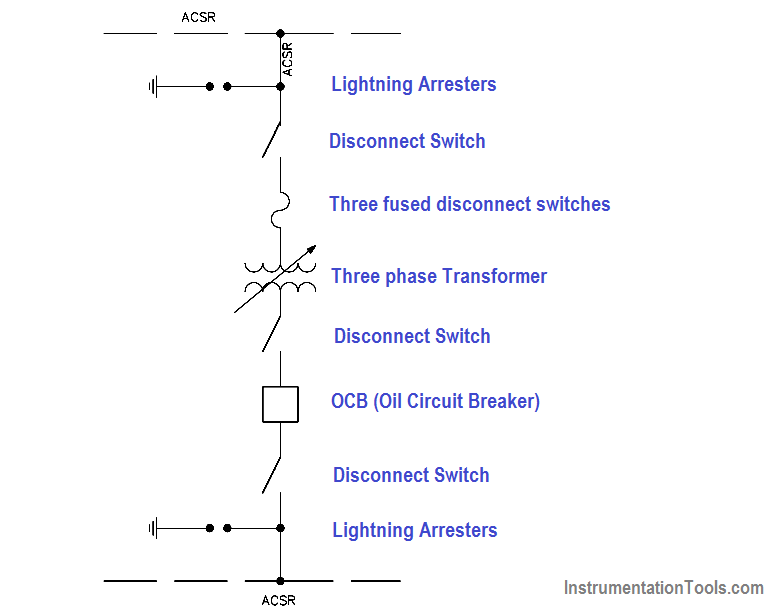
Figure 10 Single / One-Line Diagram

Don't Miss Our Updates
Be the first to get exclusive content straight to your email.
We promise not to spam you. You can unsubscribe at any time.
Invalid email address
You've successfully subscribed !

Continue Reading

Multimeter & Megger Principle
Three Phase AC Generators
Synchronous Motors
Parallel Circuit
How to Measure Specific Gravity of Battery
4-Wire, Three-Phase Wye Wiring System
Share This Article
Facebook Whatsapp Whatsapp LinkedIn Copy Link
Share
Leave a Comment

Leave a Reply Cancel reply

Your email address will not be published. Required fields are marked *

Stay Connected

128.3kFollowersLike
69.1kFollowersFollow
210kSubscribersSubscribe
38kFollowersFollow

Categories

Explore More

DC Generator
Ohm Meter
DC Generator Theory
Generator Action in a Motor
Conductor, Insulator, Resistor and Current Flow
Types of Capacitors
Schematic Diagram
Battery Hazards

Keep Learning

Gang Switch Principle

Reading Electrical Schematics

Using Kirchhoff’s Voltage Law to find Current with one Source

Applying Kirchhoff’s Voltage Law

Calculate Power in Series RC Circuit

Calculate Power in Series RC Circuit

Electrical Component Symbols

Electrical Diagrams and Schematics

Left-Hand Rule for Generators

Starting of DC Motors

Simple RC Circuit

Impedance in RC Circuits

Auto Transformer Schematic

Classification of Transformers

Forward Bias

Rectifiers, Forward Bias and Reverse Bias

Learn More

Difference Between LED and LDR

Difference Between LED and LDR

Data Preparation for AI

Data Preparation for AI: For Successful Machine Learning

How a Multi Color LED Works

How a Multi Color LED Works ?

PLC Count values higher than 999

PLC Count values higher than 999

Inclined-limb Manometer Formula - 2

Inclined-limb Manometer Principle

PLC Program for motor operation based on time cycle

PLC Motor Operation based on Time Cycle Sequence – Program

How a Level Switch Works

Robotic Automation

Robotic Process Automation (RPA) in AI – Market Growth & Business Benefits

Menu

  • About
  • Privacy Policy
  • Copyright

Quick Links

  • Learn PLC
  • Helping Hand
  • Part Time Job

YouTube Subscribe

Follow US
All rights reserved. Reproduction in whole or in part without written permission is prohibited.
Welcome Back!

Sign in to your account

Username or Email Address
Password

Lost your password?