Inst ToolsInst ToolsInst Tools
  • Courses
  • Automation
    • PLC
    • Control System
    • Safety System
    • Communication
    • Fire & Gas System
  • Instrumentation
    • Design
    • Pressure
    • Temperature
    • Flow
    • Level
    • Vibration
    • Analyzer
    • Control Valve
    • Switch
    • Calibration
    • Erection & Commissioning
  • Interview
    • Instrumentation
    • Electrical
    • Electronics
    • Practical
  • Q&A
    • Instrumentation
    • Control System
    • Electrical
    • Electronics
    • Analog Electronics
    • Digital Electronics
    • Power Electronics
    • Microprocessor
  • Request
Search
  • Books
  • Software
  • Projects
  • Process
  • Tools
  • Basics
  • Formula
  • Power Plant
  • Root Cause Analysis
  • Electrical Basics
  • Animation
  • Standards
  • 4-20 mA Course
  • Siemens PLC Course
Reading: How a Multi Color LED Works ?
Share
Font ResizerAa
Inst ToolsInst Tools
Font ResizerAa
  • Courses
  • Design
  • PLC
  • Interview
  • Control System
Search
  • Courses
  • Automation
    • PLC
    • Control System
    • Safety System
    • Communication
    • Fire & Gas System
  • Instrumentation
    • Design
    • Pressure
    • Temperature
    • Flow
    • Level
    • Vibration
    • Analyzer
    • Control Valve
    • Switch
    • Calibration
    • Erection & Commissioning
  • Interview
    • Instrumentation
    • Electrical
    • Electronics
    • Practical
  • Q&A
    • Instrumentation
    • Control System
    • Electrical
    • Electronics
    • Analog Electronics
    • Digital Electronics
    • Power Electronics
    • Microprocessor
  • Request
Follow US
All rights reserved. Reproduction in whole or in part without written permission is prohibited.
Inst Tools > Blog > Electronic Devices & Circuits > How a Multi Color LED Works ?

How a Multi Color LED Works ?

Last updated: September 11, 2019 9:52 am
Editorial Staff
Electronic Devices & Circuits
No Comments
Share
1 Min Read
SHARE

A LED that emits one colour when forward biased and another colour when reverse biased is called a multicolour LED.

One commonly used schematic symbol for these LEDs is shown in below figure.

How a Multi Color LED Works

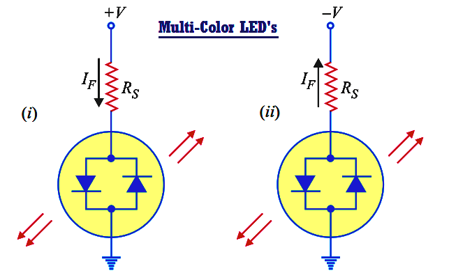
Multi Color LED’s actually contain two pn junctions that are connected in reverse-parallel i.e. they are in parallel with anode of one being connected to the cathode of the other.

 If positive potential is applied to the top terminal as shown in Fig. (i), the pn junction on the left will light.  Note that the device current passes through the left pn junction.

If the polarity of the voltage source is reversed as shown in Fig. (ii), the pn junction on the right will light.  Note that the direction of device current has reversed and is now passing through the right pn junction.

Multicolour LEDs are typically red when biased in one direction and green when biased in the other. If a multicolour LED is switched fast enough between two polarities, the LED will produce a third colour.

A red/green LED will produce a yellow light when rapidly switched back and forth between biasing polarities.

Don't Miss Our Updates
Be the first to get exclusive content straight to your email.
We promise not to spam you. You can unsubscribe at any time.
Invalid email address
You've successfully subscribed !

Continue Reading

Freewheeling Diode Working Principle
Cathode Ray Tube (CRT)
What is Kirchhoff’s Current Law
Power MOSFET Safe Operating Area
Combining Independent Current Sources in Parallel
Transistors Questions & Answers
Share This Article
Facebook Whatsapp Whatsapp LinkedIn Copy Link
Share
Leave a Comment

Leave a Reply Cancel reply

Your email address will not be published. Required fields are marked *

Stay Connected

128.3kFollowersLike
69.1kFollowersFollow
210kSubscribersSubscribe
38kFollowersFollow

Categories

Explore More

Basic Electronics Questions & Answers
Optoisolator Working Principle
Bipolar Junction Transistor Construction
Operation of Zener Diode Voltage Regulator
What is a Filter Circuit ?
Capacitor Filter Working Principle
Classification of Bridge Circuits
PMMC Temperature Compensation

Keep Learning

Testing a defective transistor

Testing a Transistor with a Digital Multimeter

Combining Independent Voltage Sources in Series

Combining Independent Voltage Sources in Series

phototransistor symbols

Phototransistor Working Principle

Capacitor Filter Operation

Capacitor Filter Operation

Permanent magnet moving coil instruments (PMMC)

Permanent Magnet Moving Coil Instruments (PMMC)

Diodes Voltage Quadrupler

Diodes Voltage Quadrupler

diode-clamper-circuit

Full Wave Voltage Doubler using Diodes

Diode-testing-with-multimeter

How to Test a Diode using Multimeter

Learn More

Power Systems Questions & Answers

Power Systems MCQ Series 20

Main Functions of a Multimeter

Interesting Multimeter Functions (And What They Really Do)

Self-balancing Pneumatic Instrument Principles - 3

Self-balancing Pneumatic Instrument Principles

Flow Meters Troubleshooting

Turbine Flow Meters Troubleshooting

Calculate Density and Specific Gravity

Calculate Density and Specific Gravity

DC Motors Objective Questions and Answers

175+ DC Motors Objective Questions and Answers

PLC Engineers Interview Questions

PLC SCADA Engineers Interview Questions and Answers

Erratic H2 Flow Rotameter

Erratic H2 Flow Rotameter

Menu

  • About
  • Privacy Policy
  • Copyright

Quick Links

  • Learn PLC
  • Helping Hand
  • Part Time Job

YouTube Subscribe

Follow US
All rights reserved. Reproduction in whole or in part without written permission is prohibited.
Welcome Back!

Sign in to your account

Username or Email Address
Password

Lost your password?