This article will discuss the SIMATIC STEP 7 PLC program for product sorting and then the heating process. The Industrial Oven Conveyor Control System is an automated system designed to process products based on color. This system is equipped with two conveyors integrated with color sensors. The first conveyor operates continuously, while the second conveyor is activated based on the detection of a product from the first conveyor. The color sensor will detect the incoming product and send a signal to the control system to adjust the oven temperature according to the product type. The system is also equipped with a counter to count the number of processed products.
Program Objective

Initialization:
The system starts.
- Conveyor 1 Starts running continuously.
- The oven is ready with an initial temperature of 38 degrees.
Product Detection:
The sensor detects a product carried by Conveyor 1.
Activation of Conveyor 2:
If a product is detected, Conveyor 2 starts moving to carry the product into the oven.
Temperature Adjustment:
- Red Product: If the detected product is Red, the oven temperature is increased to 65 degrees.
- Blue Product: If the detected product is Blue, the oven temperature is increased to 80 degrees.
Heating Process:
The product is carried by Conveyor 2 through the oven at the set temperature.
Product Counting:
When the product exits the oven, the system counts the number of processed products.
Return to Initial Temperature:
After all products have been processed and no new products are detected, the oven temperature returns to 38 degrees.
Reset Counter: Product counting data will be reset when the “Reset button” is pressed.
IO Mapping Details in SIMATIC STEP 7 Program
| S.No. | Name TAG | Input (I) | Output (Q) | Memory Words | Memory Bits |
|---|---|---|---|---|---|
| 1 | START | I0.0 | |||
| 2 | STOP | I0.1 | |||
| 3 | BLUE_SENS | I0.2 | |||
| 4 | GREEN_SENS | I0.3 | |||
| 5 | SENS_OUT | I0.4 | |||
| 6 | RESET_COUNTER | I0.5 | |||
| 7 | CONVEYOR_1 | Q0.0 | |||
| 8 | OVEN | Q0.1 | |||
| 9 | CONVEYOR_2 | Q0.2 | |||
| 10 | COUNTER | MW6 | |||
| 11 | SV_TEMPERATURE | MW4 | |||
| 12 | SYSTEM_ON | M0.0 | |||
| 13 | IR1_CONV2_ON | M0.1 | |||
| 14 | IR2_CONV2_ON | M0.2 | |||
| 15 | Temp_Memory | M0.3 |
Product Sorting and Heating Process
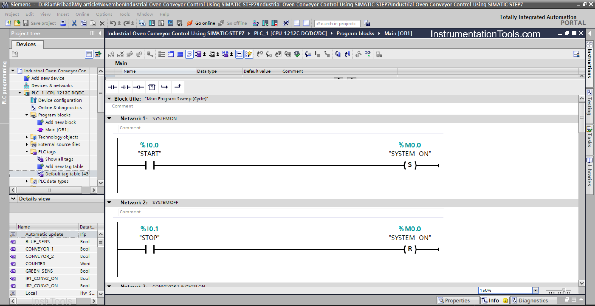
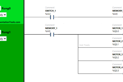
NETWORK 1 (SYSTEM ON)
In this network, the memory bit SYSTEM_ON (M0.0) will be in a HIGH state when the START (I0.0) button is pressed. Even if the START (I0.0) button is released, the memory bit SYSTEM_ON (M0.0) will remain in a HIGH state. This is because it uses the SET OUTPUT instruction.
NETWORK 2 (SYSTEM OFF)
In this network, if the STOP button (I0.1) is pressed, then the memory bit SYSTEM_ON (M0.0) will be in a LOW state. This is because it uses the RESET OUTPUT instruction.

NETWORK 3 (CONVEYOR 1 & OVEN ON)
In this Network, the outputs CONVEYOR_1 (Q0.0) and OVEN (Q0.1) will be ON if the NO contact of the memory bit SYSTEM_ON (M0.0) is in a HIGH state.
The memory word SV_TEMPERATURE (MW4) will have a value of “38” due to the MOV instruction.
The MOV instruction will stop moving the value “38” to the memory word SV_TEMPERATURE (MW4) after the NC contacts of memory bits IR1_CONV2_ON (M0.1) and IR2_CONV2_ON (M0.2) are in a HIGH state.

NETWORK 4 (SEQUENCE 1)
In this Network, the memory bit IR1_CONV2_ON (M0.1) will be in a HIGH state when the NO contact of memory bit SYSTEM_ON (M0.0) and Sensor BLUE_SENS (I0.2) are in a HIGH state.
The memory word SV_TEMPERATURE (MW4) will have a value of “65” due to the MOV instruction.
The memory bit IR1_CONV2_ON (M0.1) will remain in a HIGH state even if the sensor BLUE_SENS (I0.2) is in a LOW state. Because it uses Latching.
And the memory bit IR1_CONV2_ON (M0.1) will become LOW when the NC contact of Sensor SENS_OUT(I0.4) is in a HIGH state.
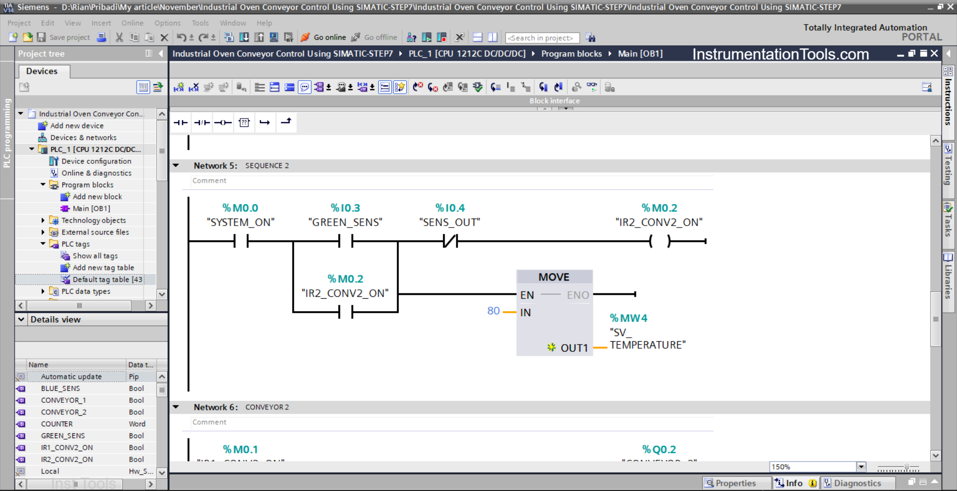
NETWORK 5 (SEQUENCE 2)
In this Network, the memory bit IR2_CONV2_ON (M0.2) will be in a HIGH state when the NO contact of memory bit SYSTEM_ON (M0.0) and Sensor GREEN_SENS (I0.3) are in a HIGH state.
The memory word SV_TEMPERATURE (MW4) will have a value of “80” due to the MOV instruction.
The memory bit IR2_CONV2_ON (M0.2) will remain in a HIGH state even if the sensor GREEN_SENS (I0.3) is in a LOW state. Because it uses Latching.
And the memory bit IR2_CONV2_ON (M0.2) will become LOW when the NC contact of Sensor SENS_OUT (I0.4) is in a HIGH state.
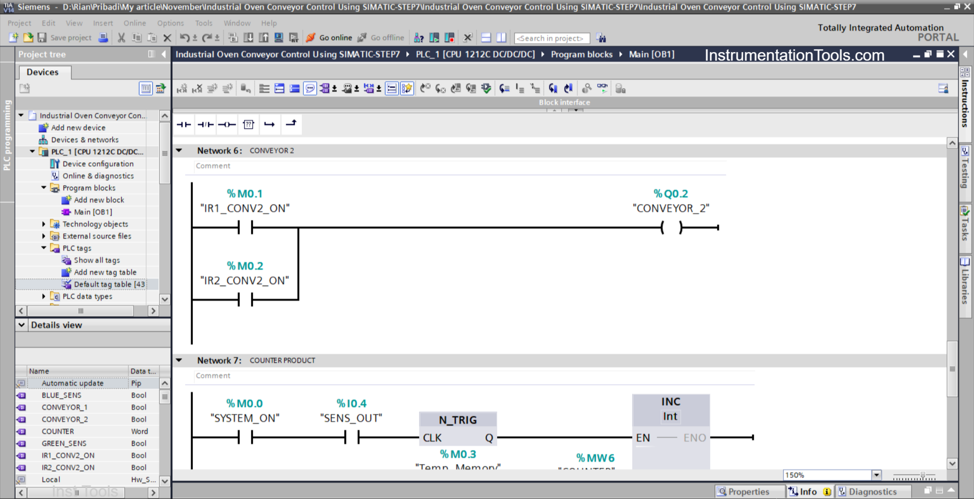
NETWORK 6 (CONVEYOR 2)
In this Network, if the NO contact of memory bit IR1_CONV2_ON (M0.1) or IR2_CONV2_ON (M0.2) is in a HIGH state, then Output CONVEYOR_2 (Q0.2) will be turned ON.

NETWORK 7 (COUNTER PRODUCT)
In this Network, the value in the memory word COUNTER (MW6) will increment (+1) if the NO contact of the memory bit SYSTEM_ON (M0.0) and the sensor SENS_OUT (I0.4) are in a HIGH state.
NETWORK 8 (RESET COUNTER)
In this Network, the MOV instruction will move the value “0” to the memory word COUNTER (MW6) when the RESET_COUNTER button (I0.5) is pressed.
Read Next:
- Siemens STEP 7 PLC for Liquid Level Alarm and Control
- SIMATIC PLC Programming for Aquaculture System
- Vehicle Washing PLC Project: Spray, Brush, Rinse, Dry
- PLC Programming for Fruit Sorting by Weight and Color
- Automated Waste Sorting System Using PLC Program