Inst ToolsInst ToolsInst Tools
  • Courses
  • Automation
    • PLC
    • Control System
    • Safety System
    • Communication
    • Fire & Gas System
  • Instrumentation
    • Design
    • Pressure
    • Temperature
    • Flow
    • Level
    • Vibration
    • Analyzer
    • Control Valve
    • Switch
    • Calibration
    • Erection & Commissioning
  • Interview
    • Instrumentation
    • Electrical
    • Electronics
    • Practical
  • Q&A
    • Instrumentation
    • Control System
    • Electrical
    • Electronics
    • Analog Electronics
    • Digital Electronics
    • Power Electronics
    • Microprocessor
  • Request
Search
  • Books
  • Software
  • Projects
  • Process
  • Tools
  • Basics
  • Formula
  • Power Plant
  • Root Cause Analysis
  • Electrical Basics
  • Animation
  • Standards
  • 4-20 mA Course
  • Siemens PLC Course
Reading: Transistor as an Amplifier in Common Emitter
Share
Notification Show More
Font ResizerAa
Inst ToolsInst Tools
Font ResizerAa
  • Courses
  • Design
  • PLC
  • Interview
  • Control System
Search
  • Courses
  • Automation
    • PLC
    • Control System
    • Safety System
    • Communication
    • Fire & Gas System
  • Instrumentation
    • Design
    • Pressure
    • Temperature
    • Flow
    • Level
    • Vibration
    • Analyzer
    • Control Valve
    • Switch
    • Calibration
    • Erection & Commissioning
  • Interview
    • Instrumentation
    • Electrical
    • Electronics
    • Practical
  • Q&A
    • Instrumentation
    • Control System
    • Electrical
    • Electronics
    • Analog Electronics
    • Digital Electronics
    • Power Electronics
    • Microprocessor
  • Request
Follow US
All rights reserved. Reproduction in whole or in part without written permission is prohibited.
Inst Tools > Blog > Electronic Devices & Circuits > Transistor as an Amplifier in Common Emitter

Transistor as an Amplifier in Common Emitter

Last updated: September 27, 2016 3:02 pm
Editorial Staff
Electronic Devices & Circuits
1 Comment
Share
3 Min Read
SHARE

The below Fig. shows the common emitter npn amplifier circuit. Note that a battery VBB is connected in the input circuit in addition to the signal voltage. This d.c. voltage is known as bias voltage and its magnitude is such that it always keeps the emitter-base junction forward *biased regardless of the polarity of the signal source.

Transistor as an Amplifier in Common Emitter

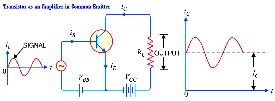
Operation. During the positive half-cycle of the signal, the forward bias across the emitter-base junction is increased. Therefore, more electrons flow from the emitter to the collector via the base. This causes an increase in collector current. The increased collector current produces a greater voltage drop across the collector load resistance RC. However, during the negative half-cycle of the signal, the forward bias across emitter-base junction is decreased. Therefore, collector current decreases. This results in the decreased output voltage (in the opposite direction). Hence, an amplified output is obtained across the load.

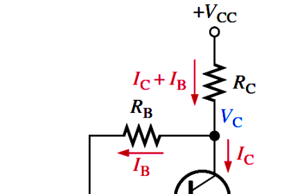
Analysis of collector currents. When no signal is applied, the input circuit is forward biased by the battery VBB. Therefore, a d.c. collector current IC flows in the collector circuit. This is called zero signal collector current. When the signal voltage is applied, the forward bias on the emitter-base junction increases or decreases depending upon whether the signal is positive or negative. During the positive half-cycle of the signal, the forward bias on emitter-base junction is increased, causing total collector current iC to increase. Reverse will happen for the negative half-cycle of the signal.

Above Fig. (right) shows the graph of total collector current iC versus time. From the graph, it is clear that total collector current consists of two components, namely ;

(i) The d.c. collector current IC (zero signal collector current) due to bias battery VBB. This is the current that flows in the collector in the absence of signal.

(ii) The a.c. collector current ic due to signal. Total collector current, iC = ic + IC

The useful output is the voltage drop across collector load RC due to the a.c. component ic. The purpose of zero signal collector current is to ensure that the emitter-base junction is forward biased at all times.

Don't Miss Our Updates
Be the first to get exclusive content straight to your email.
We promise not to spam you. You can unsubscribe at any time.
Invalid email address
You've successfully subscribed !

Continue Reading

Transistor Cut off, Saturation & Active Regions
Basic Transistor Amplifier Circuit Principle
Band Gap for Semiconductor Materials
Amplifiers Questions & Answers
Electron Gun of Cathode Ray Tube
Cathode Ray Tube (CRT)
Share This Article
Facebook Whatsapp Whatsapp LinkedIn Copy Link
Share
1 Comment
  • Sumanjali says:
    April 7, 2022 at 4:36 pm

    It is very useful to me, the points guided by you is good. Thank you

    Reply

Leave a Reply Cancel reply

Your email address will not be published. Required fields are marked *

Stay Connected

128.3kFollowersLike
69.1kFollowersFollow
210kSubscribersSubscribe
38kFollowersFollow

Categories

Explore More

Methods of Transistor Biasing
Seven Segment Display Working Principle
Ideal Diode Characteristics
Laser Diode Working Principle
Operation of Zener Diode Voltage Regulator
Testing a Transistor with a Digital Multimeter
Full Wave Rectifier
Comparison of Half wave Rectifiers and Full wave Rectifiers

Keep Learning

Transistor Voltage Divider Bias

Transistor Voltage Divider Bias

Photodiode as Variable Resistance Device

Photodiode as Variable Resistance Device

Fluorescent Screen of CRT

CRT Fluorescent Screen

Shockley Diode Working Principle

Shockley Diode Working Principle

Types of Resistors

Types of Resistors

Bipolar Junction Transistor Construction

Bipolar Junction Transistor Construction

principle of time base generator

Time Base Generator

Troubleshooting a Biased Transistor

Troubleshooting a Biased Transistor

Learn More

FMCW radar principle

TDR & FMCW Radar Level Transmitters Principle

Bellows-Type Steam Trap

Bellows Steam Trap

DTS sensors

Distributed Temperature Sensors (DTS) in Power Lines

Digital Control Systems

Z & S Domain Relationship

Manual Call Point Testing Procedure

Manual Call Point Testing Procedure

Types of Wireless Technologies in Industrial Automation

Types of Wireless Technologies in Industrial Automation

Electrical Voltage and current Signals

Electrical Voltage and current Signals

Electrification in Mining Industry

Electrification in Mining Industry

Menu

  • About
  • Privacy Policy
  • Copyright

Quick Links

  • Learn PLC
  • Helping Hand
  • Part Time Job

YouTube Subscribe

Follow US
All rights reserved. Reproduction in whole or in part without written permission is prohibited.
Welcome Back!

Sign in to your account

Username or Email Address
Password

Lost your password?