This article explains the application of sequential system concepts in PLC programming using Siemens TIA-Portal. The system is designed to control the sequential activation of outputs at specific time intervals using only a single button as the controller. Data comparison functions are used to manage transitions between sequences in the program. The compared data can be reset if needed to stop the sequence process. This program consists of three sequences, and the system will automatically stop after reaching the final sequence.
Program Objective
Step-Step System Description:
- Standby Mode: The system remains in standby mode until the Start button is pressed.
- Sequence Control: The sequence transition can be controlled by pressing the Run button. Each time the Run button is pressed, the data value in the Sequence memory word increases by (+1).
- Lamp Operation Based on Sequence:
- Sequence 1: If the data value in the Sequence memory word is 1, Lamp 1 will turn ON for 3 seconds, then turn OFF.
- Sequence 2: If the data value in the Sequence memory word is 2, Lamp 2 will turn ON for 4 seconds, then turn OFF.
- Sequence 3: If the data value in the Sequence memory word is 3, Lamp 3 will turn ON for 5 seconds, then turn OFF.
- Automatic Reset: If the data value in the Sequence memory word exceeds 3, the system will automatically reset the data value to 0.
- Manual Reset: The data in the Sequence memory word can also be reset to 0 by pressing the Reset button.
Sequential Control Logic
Note/Correction: In Network 5, it should be Timer3 (DB3). The memory bit address used in Network 5 is ir_timer3.
Mapping Details
| S.No. | Comment | Input (I) | Output(Q) | Memory Bits | Memory Word | Timers |
| 1 | START | I0.0 | ||||
| 2 | STOP | I0.1 | ||||
| 3 | RUN_SYSTEM | I0.2 | ||||
| 4 | RESET_SEQUENCE | I0.3 | ||||
| 5 | LAMP1 | Q0.0 | ||||
| 6 | LAMP2 | Q0.1 | ||||
| 7 | LAMP3 | Q0.2 | ||||
| 8 | TIMER1 | DB1 | ||||
| 9 | TIMER2 | DB2 | ||||
| 10 | TIMER3 | DB3 | ||||
| 11 | SYSTEM_ON | M0.0 | ||||
| 12 | IR_TIMER1 | M0.1 | ||||
| 13 | IR_TIMER2 | M0.2 | ||||
| 14 | IR_TIMER3 | M0.3 | ||||
| 15 | TEMP_DATA | M0.4 | ||||
| 16 | SEQUENCE | MW2 |
Siemens TIA Portal Logic
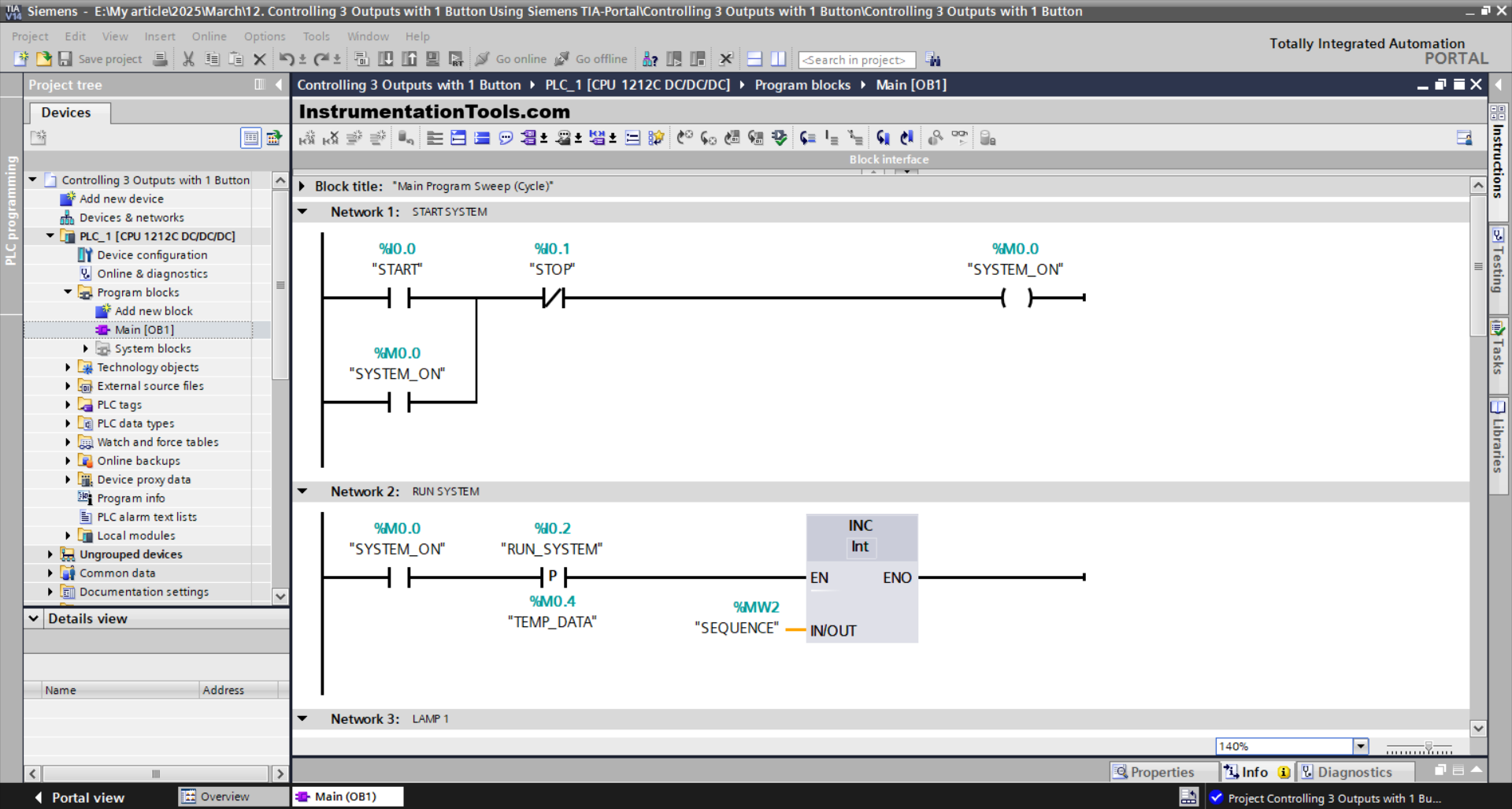
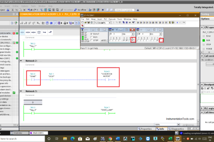
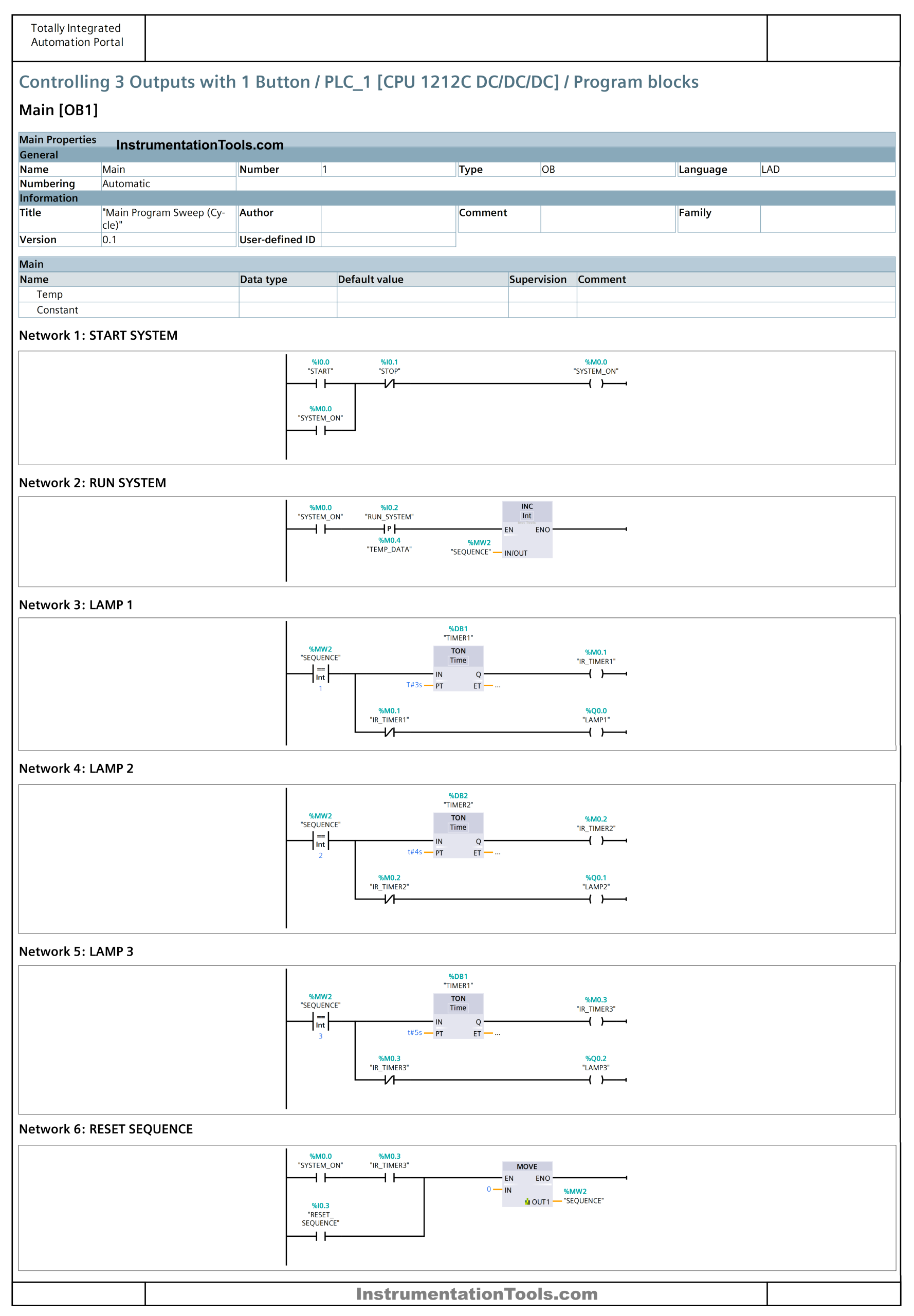
NETWORK 1 (START)
In this Network, the memory bit SYSTEM_ON (M0.0) changes to a HIGH state when the START (I0.0) button is pressed. Even though the START (I0.0) button has been released, the memory bit SYSTEM_ON (M0.0) will remain in a HIGH state. Because it uses Latching.
If the STOP (I0.1) button is pressed, the memory bit SYSTEM_ON (M0.0) will be in a LOW state.
NETWORK 2 (RUN SYSTEM)
The value in the memory word SEQUENCE (MW2) will increase (+1) when the NO contact of the memory bit SYSTEM_ON (M0.0) is in a HIGH state and the RUN_SYSTEM (I0.2) button is pressed.
The INC instruction will add (+1) to the data in the memory word SEQUENCE (MW2).
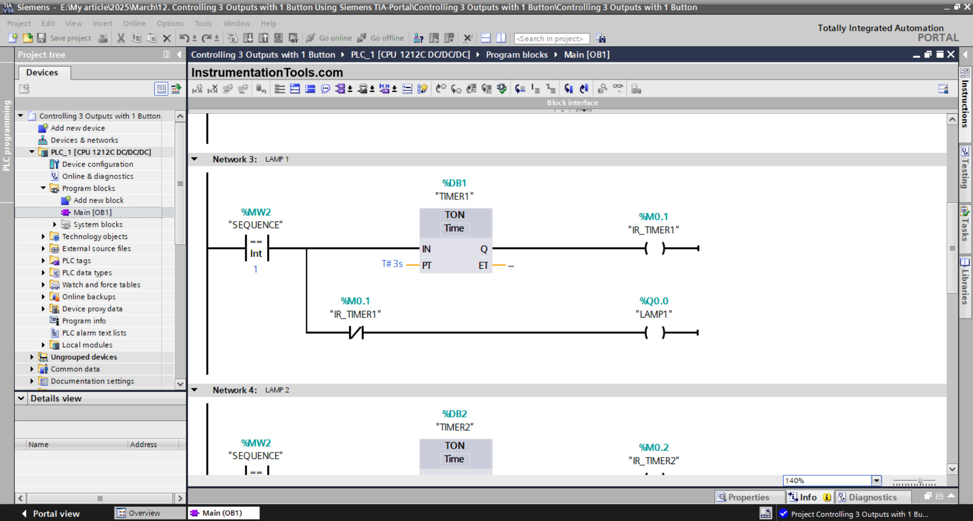
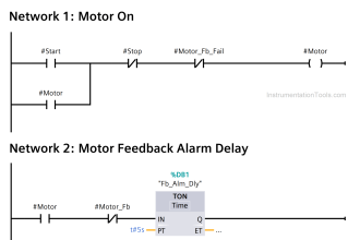
NETWORK 3 (LAMP 1)
The output LAMP1 (Q0.0) will be ON when the value in the memory word SEQUENCE (MW2) is Equal To “1.
The TIMER1 (DB1) timer will count up to 3 seconds, and when the timer has finished counting, the memory bit IR_TIMER1 (M0.1) will be in a HIGH state.
Next, the output LAMP1 (Q0.0) becomes OFF due to the Interlock of the memory bit IR_TIMER1 (M0.1).
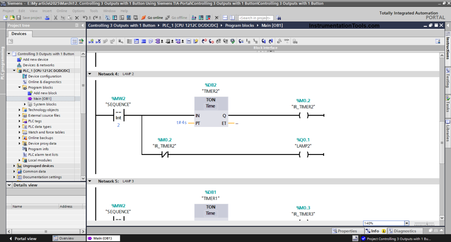
NETWORK 4 (LAMP 2)
The output LAMP2 (Q0.1) will be ON when the value in the memory word SEQUENCE (MW2) is Equal To “2”.
The timer TIMER2 (DB2) will count up to 4 seconds, and when the timer has finished counting, the memory bit IR_TIMER2 (M0.2) will be in a HIGH state.
Next, the output LAMP2 (Q0.1) becomes OFF due to the Interlock of the memory bit IR_TIMER2 (M0.2).
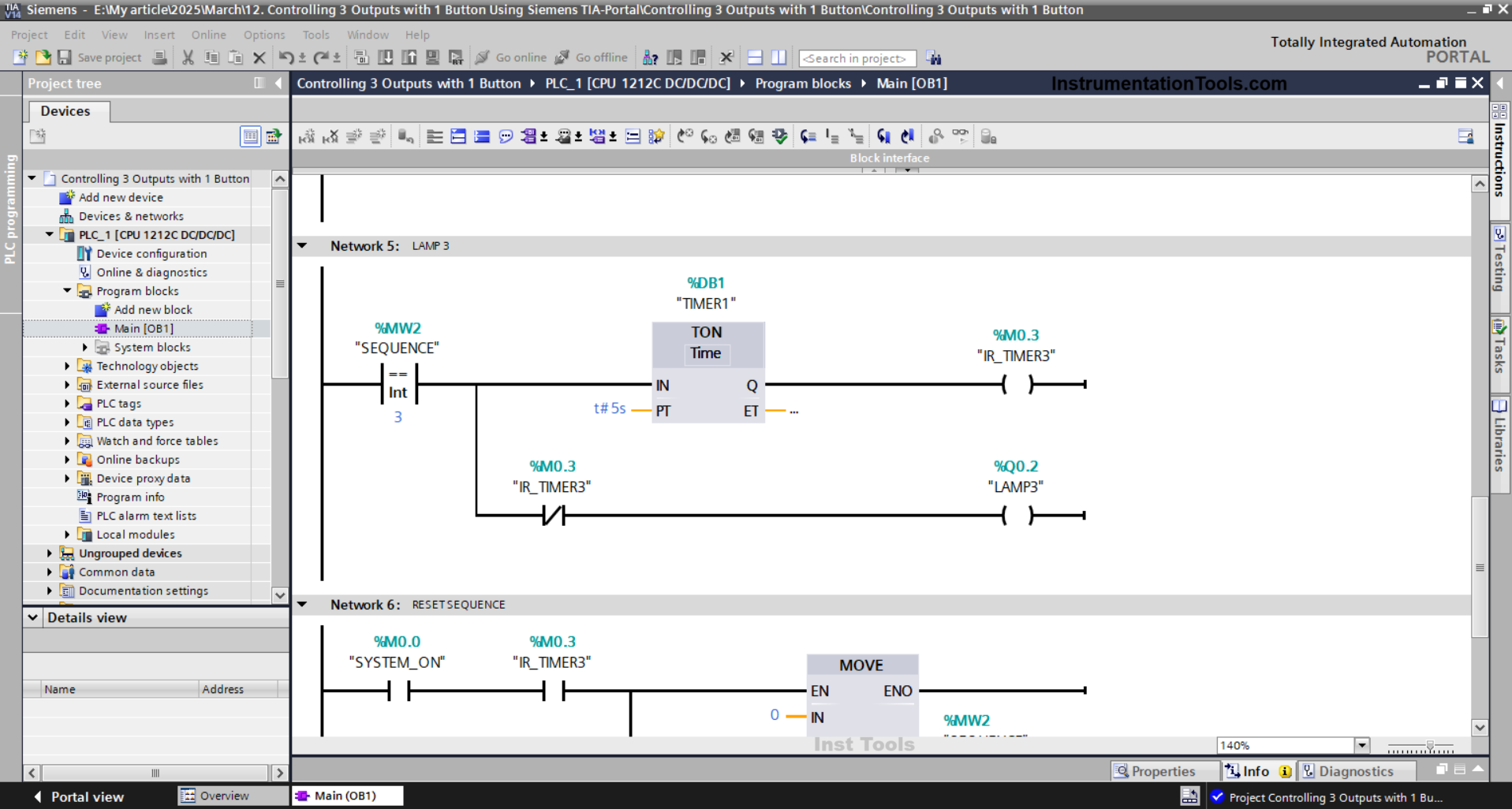
NETWORK 5 (LAMP 3)
The output LAMP3 (Q0.2) will be ON when the value in the memory word SEQUENCE (MW2) is Equal To “3”.
The timer TIMER1 (DB2) starts counting up to 5 seconds, and when the timer has finished counting, the memory bit IR_TIMER3 (M0.3) will be in a HIGH state.
Next, the output LAMP3 (Q0.2) becomes OFF due to the Interlock of the memory bit IR_TIMER3 (M0.3).
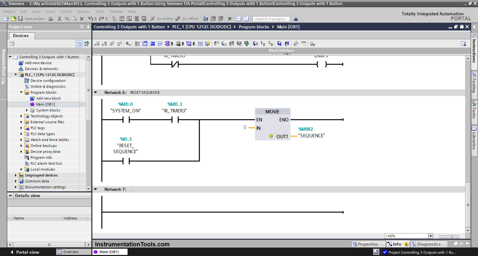
NETWORK 6 (RESET SEQUENCE)
In this Network, the memory word SEQUENCE (MW2) becomes “0” when the NO contact of the memory bits SYSTEM_ON (M0.0) and IR_TIMER3 (M0.3) are in HIGH state, or if the RESET_SEQUENCE (I0.3) button is pressed.
The MOVE instruction will move the value “0” to the memory word SEQUENCE (MW2).
Read Next:
- PLC Program for Sequential Motor Control
- Program for Light Sequences using Timers
- Structured Text Sequential Process Data Storage
- Run 4 Motors Sequentially from 1 Push button
- PLC Programming for the Pneumatic Valves