Servo-operated float level measurement systems uses fluid displacement for continuous level measurement. This method is considered more accurate than wire-guided float systems and surface detector (plumb-bob) systems.
Servo Level Measurement

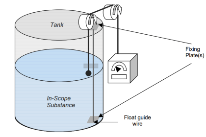
The servo gauge is used to move a displacer that is continually measuring the liquid in the tank. This is done by driving the displacer through the tank’s open space until it makes contact with the liquid surface.
As the liquid level in the tank changes, the system always aims to maintain the displacer in equilibrium, which produces the level measurement. In addition to performing the level measurement, this type of system is capable of raising alarms, such as high-high, low-low.
The material composition of the float can have an effect on the accuracy of the level measurement.
Magnetic floats are generally used in continuous float type level detectors. Of these floats, the greatest measurement accuracy is achieved with magnetostrictive technology.
Magnetic disc float level detectors are favored as a very accurate device for liquid level measurement. This type of level measuring system is normally intrinsically safe and measures continuously.
This method has a long and successful history of being implemented in ‘clean’ measurement applications such as the gasoline storage industry. The initial setup of this type of system is critical in ensuring an accurate level measurement is achieved.
The setup process requires the tank to be manually dipped. This allows for offsets to be determined and applied to the instrumentation appropriately. Correct setup and maintenance do allow servo-operated float systems to be used in custody transfer, inventory, and density measurement applications.
Although this is a well-established level measurement method there are still a number of limitations with this method.
For example, to provide a reliable level measurement consistently, this type of system requires a high level of maintenance and cleaning to ensure the tank contents do not penetrate the system instruments. However, if this is adhered to, servo-operated float systems can be reliable and highly accurate.
Servo-operated float systems are also fragile instruments. Vibration caused by people walking or even standing on a tank roof to which they are attached can cause the instrument to bounce and fall out of calibration.
Wire snapping is another common problem with this type of system. However, this fault is normally instantly acknowledged. In a stilling well, the displacer may rest on the side of the pipe if, for example, the tank foundation subsides.
It is common practice in the industry to test this type of level measurement device by manually driving the float to the top of the tank and then allowing the float to return down to the liquid surface. This test method is used when it is suspected that the level measurement provided is incorrect.
It is a simple initial check to perform instead of dip taping the tank. Modern servo-operated float gauges have functions built into them to drive the float to the top to ensure a measurement occurs. This and other similar features are built into these newer gauges to make them readily testable. This aims to overcome the systems not being tested because of the perceived complexity of the systems by the operators.
The latest version of the technology
Currently, servo gauge level measurement systems are approved by a number of European governments and agencies for custody transfer because of the accuracy that these measurement systems can achieve. Accuracy in the order of mm can be achieved using servo-operated float gauges for level measuring gasoline.
The perceived problems with servo-operated float level measurement systems fall into the category of maintenance and mechanical wear:
Maintenance issues
The activities involved are not complex but do require attention whilst maintenance is being performed. Once maintenance has been performed, it must be ensured that the gauge is behaving as expected, and a balance weight calibration is performed to ensure that the level measurement is accurate.
Gasoline does not have a major detrimental effect on servo-operated float gauge systems as long as care is taken to ensure that suitable materials are used for seals and gaskets. However, the same cannot be said about the effect of biofuels.
Due to some corrosive bio-fuel additives, these gauges can be damaged. This can be problematic because some tanks may be used to store both biofuel and gasoline at different points in their service life. This change over may not be captured in a company’s management of change procedures and as such may not be subject to impact analysis or risk assessment.
Mechanical wear
This technology relies on many mechanical parts, all of which are prone to wearing out over time in service. These parts are typically the servo motors, gear train, and magnetic bearings. Wear of these parts is normally detected by erratic measurement or sticking of the float.
Annual maintenance will also allow worn parts to be identified and repaired, or replaced as required. Wear can be accelerated when the stored gasoline or other Buncefield in-scope substances come into contact with the equipment, increasing the onset of rust on metallic parts. In some cases, this could also lead to measurement offset.
For gasoline level measurement the float must be in contact with the surface of the gasoline. This is primarily required so that the sensors within the float can determine if the surface is gasoline or surface water.
Error in measurement can be caused by system software. It is likely that a failure in the software that is associated with buoyancy would lead to measurement inaccuracy.
Read Next:
- How Magnetic Level Indicator Works?
- Weight-based Level Measurement
- Micro-impulse Level Sensor
- Hydrostatic Level Measurement
- Classification of Level Sensors