Write a PLC program so that when the set push button is pressed the first bit in output word is energized and every time the step push button is pressed the next bit is energized till the last bit in the output word, when the reset push button is pressed the output word is reset to zero.
Note: the best practice to learn the PLC programming is to start writing the PLC program, take your time before you review the answer.
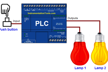
Inputs & outputs
I0.0: set Push Button (Normally open contact)
I0.1: step Push Button (Normally open contact)
I0.2: reset Push Button (Normally open contact)
Qw0: output word i.e from (Q0.0 to Q1.7)
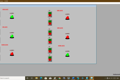
Sequential Operation of Output Bits
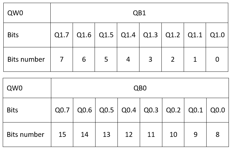
Before you start your programming you have to understand the order of bits when you hear memory word, here in the table attached you can figure out the address of any bit number.
PLC Program
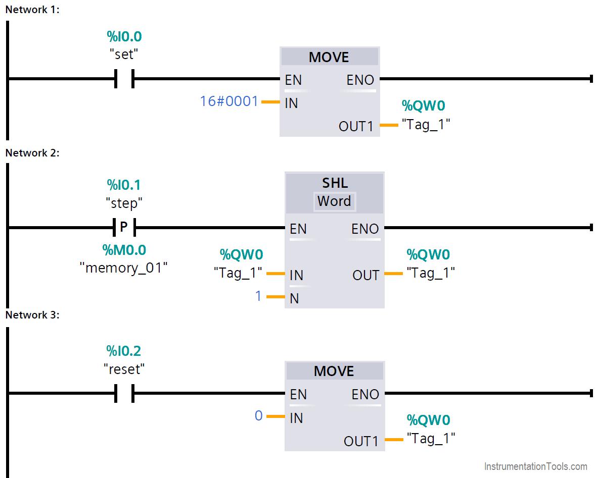
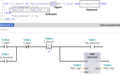
Network 1
When the set push button is pressed the hexadecimal #0001 is moved to QW0 which is equal to 0000 0000 0000 0001 which will sets the bit Q1.0 to 1.
Network 2
In every time the positive edge of step push button is detected the shift left instruction moves 1 to next bit of the QW0.
Network 3
In any time when the reset push button is pressed, 0 is moved to QW0 which will reset all the output word.
Author: Karim Ali Anwar
If you liked this article, then please subscribe to our YouTube Channel for PLC and SCADA video tutorials.
You can also follow us on Facebook and Twitter to receive daily updates.
Read Next:
- Masking in PLC
- ON and OFF Group of Outputs
- PLC Move Instruction
- Latching Function of PLC
- Push button Motor PLC Logic