SCADA systems installed in Industry facilities must be of such design or otherwise protected to withstand seismic effects as well as a shock (ground motion) and overpressure effects of weapons.
A detailed dynamic analysis should be made of the supporting structure(s) of the equipment enclosures to evaluate the magnitude of motion and acceleration established at the mounting points for each piece of SCADA equipment. Where accelerations exceed the allowable limits of equipment available, the equipment should be mounted on shock isolation platforms.
Security of SCADA Systems
SCADA equipment should be protected from the effects of dust, dirt, water, corrosive agents, other fluids and contamination by appropriate location within the industrial facility or by specifying enclosures appropriate for the environment. Care should be taken that installation methods and conduit and tubing penetrations do not compromise enclosure integrity.
Central computer or control rooms should be provided with dry agent fire protection systems or double-interlocked pre-action sprinkler systems using cross-zoned detection, to minimize the threat of accidental water discharge onto unprotected equipment.
Sensors, actuators, controllers, HMI, UPS and other SCADA equipment located throughout the industrial facility should utilize enclosures with a minimum environmental protection level of IP66 per EN 60529 or Type 4 per NEMA 250. Where thermal management issues or other equipment requirements prevent the use of such enclosures, alternate means should be provided to protect the equipment from environmental contaminants.
industrial Facility design must ensure that any industrial facility Chemical, Biological, Radiological, Nuclear or Explosive (CBRNE) protection warning, alert, or protection systems also protect SCADA systems and utility equipment areas if the mission requires the industrial facility to remain operational in a hazardous environment.
Appropriate coordination and systems integration must occur between SCADA and CBRNE protection systems so that appropriate industrial facility environmental conditions are maintained if the facility experiences a CBRNE attack or incident.
Electronic Threats
Electronic threats to SCADA systems include
- Voltage transients,
- Radio-frequency (RF) interference (RFI),
- RF weapons,
- Ground potential difference and
- Electromagnetic pulse (EMP).
These threats can all be largely mitigated by the proper design of the systems.
Voltage Transients
SCADA controllers and field devices are vulnerable to voltage transients coupled through the industrial facility power system from atmospheric (thunderstorm and lightning) effects, transmission and distribution system switching events, and switching of capacitors or inductive loads within the industrial facility.
Transient voltage surge suppression (TVSS)
Transient voltage surge suppression (TVSS) should be provided on the power supply circuits to all SCADA equipment and TVSS or optical isolation should be provided on all metallic control and communication circuits transiting between buildings. To avoid the effects of voltage transients, fiber optic cables should be used for all circuits entering or leaving an industrial facility.
Fiber media are available for most network applications at the supervisory and control levels. Field devices typically require metallic conductors, and where these must be run outside or between facilities, they should be provided with TVSS where they cross the facility perimeter.
TVSS should be specified to comply with the testing requirements of ANSI C62.34 and should be installed in accordance with IEEE 1100. The selection of TVSS locations and connections should consider that it is most effective when connected directly to the terminals of the device to be protected and provided with a direct low-impedance path to the industrial facility ground system.
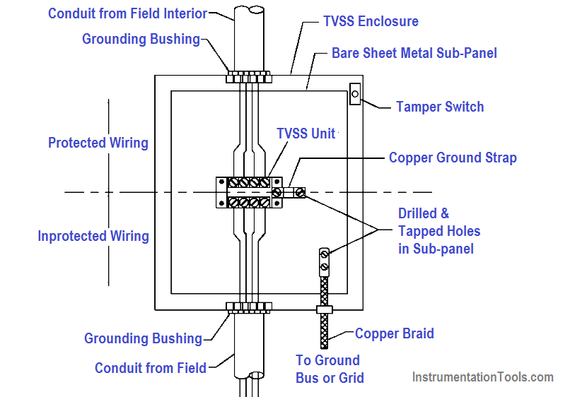
Incorrect installation methods can readily render TVSS protection ineffective. Protected and unprotected circuits should be physically segregated to avoid capacitive and inductive coupling that may bypass the TVSS.
TVSS Installation
See the below figure for an example of the correct TVSS installation.
Surge Protection
Network surge protectors should be provided at all device connections, between the equipment port and the tap.
Industry facilities often contain powerful radio frequency sources which may interfere with control system operation if coupled into control circuits.
Other ambient sources of RFI may also exist including commercial signals, electronic countermeasures (ECM), and radiated RFI from other equipment within the industrial facility.
Design and operation of SCADA systems should address measures to protect against RFI, including:
- Use of shielded twisted pair or twisted triple conductors for low-level signals.
- Installation of SCADA wiring in continuous metallic conduit systems.
- Use of metallic controller enclosures with RFI-gasketed doors.
- RFI-shielded control rooms and computer rooms.
- Maintenance practices that maintain the integrity of enclosures.
Radio Frequency Interferences
Effective shielding to limit RFI within the required limits for Industry facilities is dependent upon the grounding and bonding practices required to provide a unified industrial facility ground.
The grounding practices for the earth electrode system, the building structure, the lightning protection system, the power system, and the signal reference system must be integrated to achieve a unified ground system.
Additionally, specifications and installation designs for new equipment should include requirements to assure electromagnetic compatibility (EMC) between the equipment and the operating environment.
These requirements should serve to minimize the susceptibility of the new equipment to EMI that may be present in the operating environment as well as to limit radiated emissions by the equipment to the environment and to existing equipment.
(1) Ground potential differences within an industrial facility that may affect SCADA systems are mitigated by the proper connection of equipment to the unified grounding system that is required to be provided for all Industry facilities. This system ties the electrical service, lightning protection, and all other industrial facility grounds together into a single low-impedance ground grid.
(2) Each electrical room within the Industry facility which contains electrical equipment should be provided with a ground bus, connected to the unified ground system. SCADA equipment enclosures and internal ground buses should be connected directly to this ground bus, and should not rely solely on an equipment grounding conductor installed with the power supply circuit.
(3) All exterior metallic components which penetrate the building, such as metal piping, conduits, and ducts, should be grounded at the point of penetration. All conductive SCADA circuits entering the industrial facility from outside should be provided with TVSS, effectively grounded to the ground grid at the point of entry.
(4) Low-voltage shielded cables must be installed to avoid ground loops, which can induce interfering currents on the signal common conductor. Unless otherwise dictated by the equipment manufacturer, cable shields should be grounded at the controller end only, with the instrument end left floating and insulated.
(5) On large industrial multi-facility sites potential differences between the different facilities’ ground systems caused by atmospheric electrical activity and electrical system faults can not be prevented, in spite of their common connection through the industrial facility’s primary electrical distribution grounding system.
SCADA circuits installed between facilities on these sites should always utilize fiber optic cables or optical signal isolation at the industrial facility perimeter.
EMP Protection
The electromagnetic pulse (EMP) protection requires magnetically continuous ferrous shielding which is not provided by the enclosures of typical SCADA sensors, controllers and actuators.
For this reason, all electronic SCADA components must be assumed vulnerable to EMP and must be protected by location, external shielding, or replacement with pneumatic components.
(1) Whenever possible, all SCADA components should be located inside the Industry HEMP shield. Components that must be located outside the shield, such as sensors at an external fuel storage tank, may be provided with a local HEMP-shielded enclosure and circuits routed back to the industrial facility within a shielded conduit system or using pneumatic lines or optical fiber cable.
(2) EMP protection for non-conductive penetrations of the industrial facility shield such as pneumatic tubing and fiber optic bundles uses the principle of “waveguide below cutoff” in which the lines penetrate the industrial facility shield through a high aspect-ratio cylinder or waveguide.
The waveguide must be made of a conductive material and must be continuously welded or soldered to the primary EMP shield so that current flowing on the waveguide can be discharged to the primary EMP shield.
(3) The maximum inside diameter of penetration must be 4 inches or less to achieve a cutoff frequency of 1.47 GHz for a rectangular penetration and 1.73 GHz for a cylindrical penetration. The unbroken length of conducting material adjacent to the penetration must be a minimum of five times the diameter of the conducting material (i.e., pipe, duct) to attenuate by at least 100 dB at the required frequencies.
(4) The waveguide filter will be specified in terms of the attenuation over a specified range of frequencies. Designing Industrial Facilities to Resist Nuclear Weapons Effects: Air Entrainment, Fasteners, Penetration Protection, Hydraulic Surge Protection Devices, and EMP Protective Devices.
Equipment Location
Equipment located in electrical substations or other areas where electrical systems over 600V exist may be subject to particularly harsh transient voltage and transient electrical field conditions associated with power system faults, lightning strikes, and switching surges.
This equipment should be qualified to the industry standards applicable to the withstand capability of protective relays, ANSI C37.90.1, C37.90.2, and C37.90.3, which apply to surge voltage, radiated EMI and ESD, respectively.
Testing has shown that both STP and coaxial network communications circuits are subject to communications errors in high transient electric field conditions.
For this reason, all network communication within the substation environment should be over fiber optic circuits. Even with a fiber communication circuit, the network equipment connected to the fiber may be susceptible to radiated fields or to conducted interference at the power supply.
This equipment should be qualified for IEEE 1613, which requires automatic recovery from transient-induced communications disruptions with no false operation and no human intervention.
Other Factors
Portable RF weapons of van size down to brief-case size are now commercially available. Many of the above factors will also provide varying levels of protection against this emerging threat. For example, a HEMP shield should provide protections from RF Weapons external to the shield.
However, it will provide no protection from an RF Weapon inside the shield. Thus, a critical aspect of protection from this threat is ensuring physical security protection plans, measures and procedures recognize this threat and mitigate it.
Examples of this are to insure that industrial facility guards or security personnel are trained on this threat, are able to recognize RF Weapons, and that procedures are instituted for random or mandatory checks of all items entering the industrial facility.
Physical Security
In general, SCADA system equipment should be located inside secured areas having the same degree of security deemed appropriate for the supported systems. However, the electronic nature of these systems provides opportunities for compromise from both inside and outside the secured area that must be addressed.
HMI devices for controllers that provide access to the entire SCADA system shall use password-protected screen access with multiple levels of access control, and automatic logout routines with short time settings. Password policies for screen savers shall be in compliance with established policies.
Equipment enclosures and pull and junction boxes should be kept locked or secured with tamper-resistant hardware. Doors and covers should be provided with tamper switches or other means of detecting attempted intrusion, connected to the site security system. Tamper detection devices should be designed to detect the initial stages of access such as removal of fasteners, unlatching of doors, etc.
Raceways and enclosures for SCADA circuits external to the secured area should be designed to resist entry by unauthorized persons. Access to field wiring circuit conductors can potentially provide “back-door” entry to controllers for damaging over-voltages or transients. Outside raceways should consist of rigid steel conduits with threaded and welded joints and cast junction boxes with threaded hubs and tamper-proof covers.
Conduits exiting the secured area should also be sealed to prevent them from being used to introduce hazardous or damaging gases or fluids into enclosures within the secured area.
Communication and information networks
Connections from SCADA systems to networks extending beyond the Industry facility or between facilities on a common site introduce the threat of attacks.
These attacks are of several types:
- Unauthorized user access (hacking).
- Eavesdropping; recording of transmitted data.
- Data interception, alteration, re-transmission.
- A replay of intercepted and recorded data.
- Denial of Service; flooding the network with traffic.
The best defense against these threats is to entirely avoid network connections with other networks within or external to the industrial facility. If they must be used, data encryption techniques should be applied to all network traffic.
The following additional means of enhancing security should also be considered:
- Physically disconnect when not in use; applicable to dial-up connections for vendor service.
- Use fiber optic media which cannot be tapped or intercepted without loss of signal at the receiving end.
- One-way traffic; alarm and status transmission only with no control permitted.
Software Management and Documentation
With the modern complexity and exposure to intentional software damage that can occur in modern industrial control systems, it is a good practice to implement a Software Management and Documentation System (SMDS).
An SMDS system is software that resides on a dedicated computer on the plant network that monitors all activities of the control system. Such a system should be required for the control system in an important and complex military facility. It allows the facility administrator to do the following:
- Control who may use any SCADA application software and what actions can be performed
- Maintain a system-wide repository for historical storage of the application configuration files
- Identify exactly who has modified a control system configuration or application parameter, what they changed, where they changed it from, and when the change was made
- Assure that the control system configuration thought to be running the industrial facility actually is
- Support application restoration following a catastrophic event
- Generate views into the Software Management System for more detailed analysis of configuration changes
Software Management and Documentation systems are available now from the major suppliers of industrial control systems. Having such a system provides the following additional benefits:
- Avoids maintaining incorrect or incompatible software versions
- Assures that there are not multiple versions of software on file
- Prevents multiple users from causing a conflict somewhere on the system
- Prevents legitimate changes from being reversed or overwritten
- Supports the availability of the system at its maximum
Among the specific software that such a system would secure are:
- PLC programs
- HMI screens
- SCADA configurations
- CAD drawings
- Standard Operating Procedures (SOP’s)
- Network Configurations
Reference : This material adapted from the “Department of the Army, TM 5-601, Supervisory Control and Data Acquisition (SCADA) Systems for Command, Control, Communications, Computer, Intelligence, Surveillance, and Reconnaissance (C4ISR) Facilities, 21 January 2006.”
If you liked this article, then please subscribe to our YouTube Channel for PLC and SCADA video tutorials.
You can also follow us on Facebook and Twitter to receive daily updates.
Read Next:
Burner Management System Logic
Types of Maintenance in the field
