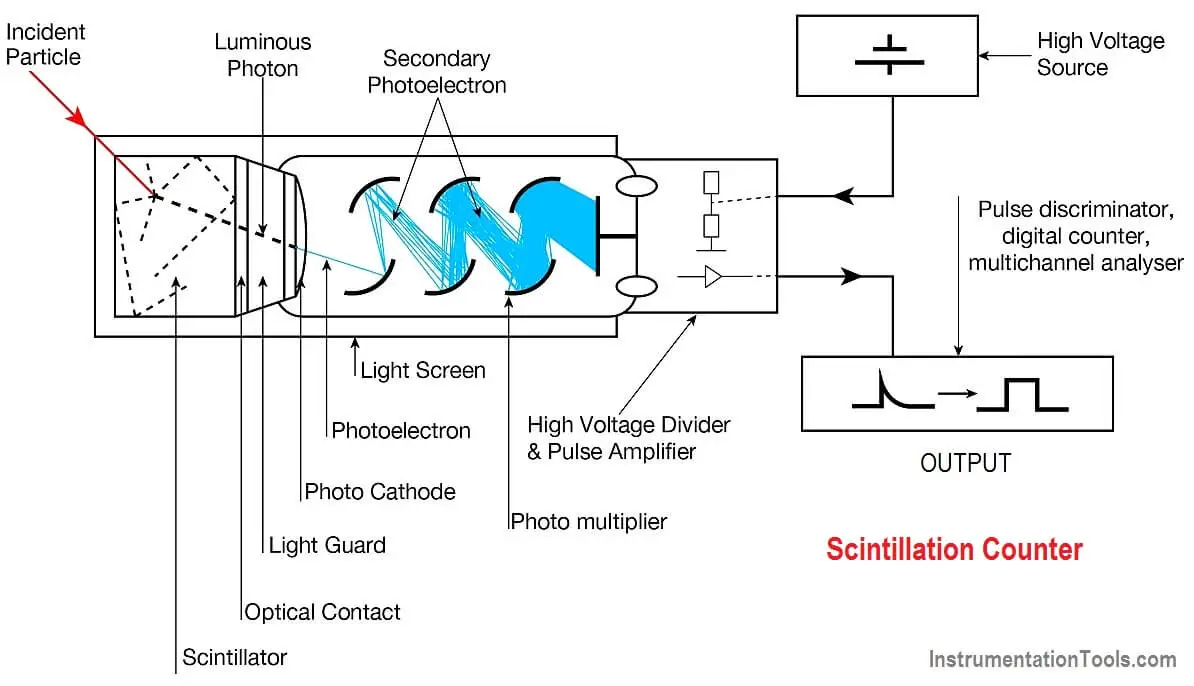
A scintillation counter is an instrument for detecting and measuring ionizing radiation by using the excitation effect of incident radiation on a scintillator material and detecting the resultant light pulses.
It consists of a scintillator that generates photons in response to incident radiation, a sensitive photomultiplier tube (PMT) which converts the light to an electrical signal and electronics to process this signal.
Scintillation Counter
Scintillation counters are widely used in radiation protection, an assay of radioactive materials and physics research because they can be made inexpensively yet with good quantum efficiency, and can measure both the intensity and the energy of incident radiation.
Operation
When an ionizing particle passes into the scintillator material, atoms are ionized along a track. For charged particles the track is the path of the particle itself. For gamma rays (uncharged), their energy is converted to an energetic electron via either the photoelectric effect, Compton scattering or pair production.
The chemistry of atomic de-excitation in the scintillator produces a multitude of low-energy photons, typically near the blue end of the visible spectrum. The number of such photons is in proportion to the amount of energy deposited by the ionizing particle.
Some portion of these low-energy photons arrive at the photocathode of an attached photo multiplier tube. The photocathode emits at most one electron for each arriving photon by the photoelectric effect.
This group of primary electrons is electrostatically accelerated and focused by an electrical potential so that they strike the first dynode of the tube. The impact of a single electron on the dynode releases a number of secondary electrons which are in turn accelerated to strike the second dynode.

Each subsequent dynode impact releases further electrons, and so there is a current amplifying effect at each dynode stage. Each stage is at a higher potential than the previous to provide the accelerating field.
The resultant output signal at the anode is in the form of a measurable pulse for each group of photons that arrived at the photocathode and is passed to the processing electronics. The pulse carries information about the energy of the original incident radiation on the scintillator.
The number of such pulses per unit time gives information about the intensity of the radiation. In some applications individual pulses are not counted, but rather only the average current at the anode is used as a measure of radiation intensity.
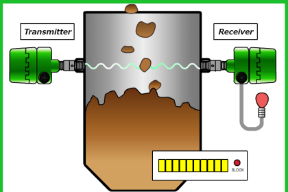
Scintillation Counter Animation
The scintillator must be shielded from all ambient light so that external photons do not swamp the ionization events caused by incident radiation. To achieve this a thin opaque foil, such as aluminized mylar, is often used, though it must have a low enough mass to minimize undue attenuation of the incident radiation being measured.
Detection materials
The scintillator consists of a transparent crystal, usually a phosphor, plastic (usually containing anthracene) or organic liquid (see liquid scintillation counting) that fluoresces when struck by ionizing radiation.
Cesium iodide (CsI) in crystalline form is used as the scintillator for the detection of protons and alpha particles. Sodium iodide (NaI) containing a small amount of thallium is used as a scintillator for the detection of gamma waves and zinc sulfide (ZnS) is widely used as a detector of alpha particles. Zinc sulfide is the material Rutherford used to perform his scattering experiment. Lithium iodide (LiI) is used in neutron detectors.
Applications
cintillation counters are used to measure radiation in a variety of applications including hand held radiation survey meters, personnel and environmental monitoring for radioactive contamination, medical imaging, radiometric assay, nuclear security and nuclear plant safety.
Reference : Wikipedia


please provide me animation of scintillation counter