Scale Instruction
SCALE_X scales the normalized real parameter VALUE where ( 0.0 <= VALUE <= 1.0 ) in the data type and value range specified by the MIN and MAX parameters:
OUT = VALUE ( MAX – MIN ) + MIN
For SCALE_X, parameters MIN, MAX, and OUT must be the same data type. NORM_X normalizes the parameter VALUE inside the value range specified by the MIN and MAX parameters:
OUT = ( VALUE – MIN ) / ( MAX – MIN ), where ( 0.0 <= OUT <= 1.0 )
Normalize Instruction
For NORM_X, parameters MIN, VALUE, and MAX must be the same data type.
Note: SCALE_X parameter VALUE should be restricted to ( 0.0 <= VALUE <= 1.0 )
If parameter VALUE is less than 0.0 or greater than 1.0:
The linear scaling operation can produce OUT values that are less than the parameter MIN value or above the parameter MAX value for OUT values that fit within the value range of the OUT data type. SCALE_X execution sets ENO = TRUE for these cases.
It is possible to generate scaled numbers that are not within the range of the OUT data type. For these cases, the parameter OUT value is set to an intermediate value equal to the least-significant portion of the scaled real number prior to final conversion to the OUT data type. SCALE_X execution sets ENO = FALSE in this case.
If parameter VALUE is less than MIN or greater than MAX, the linear scaling operation can produce normalized OUT values that are less than 0.0 or greater than 1.0. NORM_X execution sets ENO = TRUE in this case.
NORM_X and SCALE_X instructions. Explain the instructions with example.
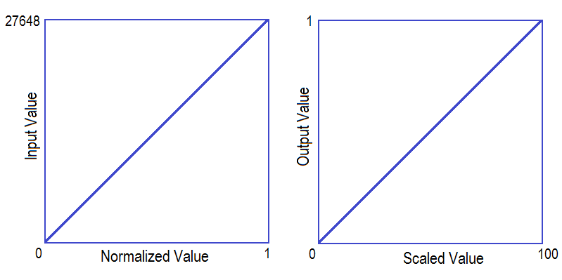
PLC ladder program explanation
General NORM_X and SCALE_X instructions are used for scaling the value or we can use this instruction in analog value scaling.
By using NORM_X instruction we can normalize the actual value in leaner scale within the value range.
For example, here the input value is 0 to 27648 and this value needs to be normalized in linear scaled value range from 0.0 to 1.0.
After this normalization of the value we can use this output as input value of the SCALE_X instruction. This instruction maps the value in required range (here 0 to 100). This instructions generally used in Siemens S7-1200 PLC.
List of Inputs/Outputs
- Register A :- For analog value (0 to 27648).
- Register B :- Out of NORM_X
- Register C :- Output value of SCALE_X instruction.
PLC Ladder Programming
NETWORK 1 :-
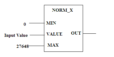
Here define MIN value and MAX value of the actual input.
For example if analog sensor is connected in the analog channel, MIN value is 0 and MAX value is 27648.
The instruction will scale the actual input value into normalized value (0.0 to 1.0).
NETWORK 2 :-
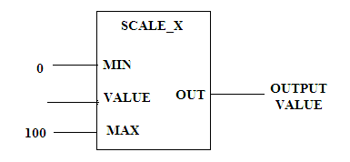
Here SCALE_X instruction is used. After normalization of the actual value, we can convert it into desired value range (0 to 100).
For example purpose, we have taken here 0 to 100 range but we can take other value also.
Note :- Above application may be different from actual application. This example is only for explanation and educational purpose only. We can implement this logic in other PLC also. This is the simple concept of NORM_X and SCALE_X, we can use this concept in other examples also.
All parameters and graphical representations considered in this example are for explanation purpose only, parameters or representation may be different in actual applications. Also all interlocks are not considered in the application.
If you liked this article, then please subscribe to our YouTube Channel for PLC and SCADA video tutorials.
You can also follow us on Facebook and Twitter to receive daily updates.
Read Next:
