Safety Requirement Specification (SRS) details the entire steps being followed in the Safety Instrumented System lifecycle.
Safety Requirement Specifications (SRS) form gives a full view of the SIS design, configuration of sensors, logic solver & Final control element, which discipline is responsible for what kind of action, etc.
International Standards IEC 61511-1 details the requirements of SRS.
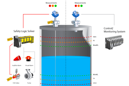
Safety Instrumented System
SRS Form is a detailed excel sheet containing complete information on the SIS applicable for the particular project.
For any project involving Safety Instrumented System (SIS) shall form a team from Production Leader, HSE Leader of respective plant together with certified Safety Instrumented System coaches along with the Design lead, Maintenance representatives & Technology center expert who is well versed with the Plant Operations.
Information shall contain a complete SIS Lifecycle study, major points per the below details.
- SIS Design Information
- SIS Verification
- SIS validation & Commissioning
- Reviews and Approvals (Different disciplines involved)
- SIS registration
- Documentation in Plant Library
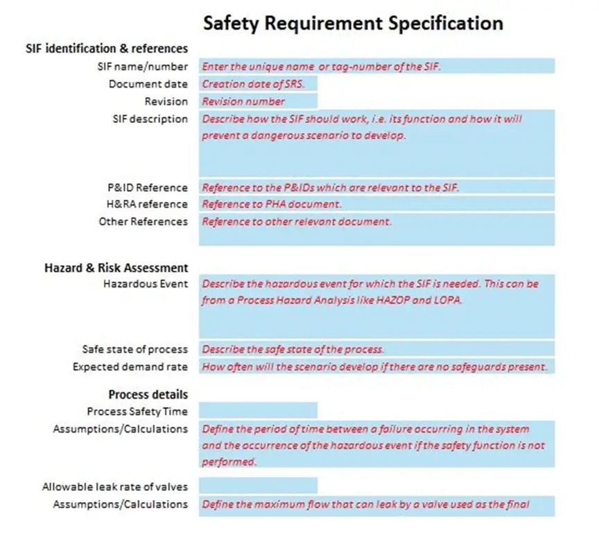
Safety Requirements Specification (SRS)
Safety Requirements Specification (SRS Form) shall be the basic document for the design, installation, and commissioning of the SIS Loops.
This SRS form shall be part of the engineering deliverable for all the projects which involve the new addition of SIS or modification of any existing SIS Loops across the plant.
SRS Form shall consist of various sections (Section 1 to 12) and each section shall be updated by different personnel of identified role profiles per plant manager / Department leader.
However, it is mandatory that the updation of different Sections of the SRS form shall be carried out in sequence (i.e Section, 1, 2, 3,…,12).
Detailed Steps of SRS
| Step Number | Description |
|---|---|
| STEP-1 | The operations representative / Process/ Process Safety Design Engineer is to identify & define the hazards related to the project, during the feasibility study of a project. |
| STEP-2 | For any projects, the need for Process Hazard Analysis and LOPA is to be identified in the Front End Engineering and documented. |
| STEP-3 | If there is a need to carry out LOPA, then the LOPA study has to be conducted by the Plant operations representative. As part of this Step, Section-1 of the Safety Requirements Specification (SRS) Form is to be filled by the Operations representative Plant Safety Engineer |
| STEP-4 | From the LOPA, the requirement of SIS loops, SIL target levels need to be finalized in the Front End Engineering itself. |
| STEP-5 | Once the SIS Loop is identified, the Instrument Protective System needs to be detailed further to ensure the appropriate functionality and capability. |
| STEP-6 | This is to ensure that the required Safety Instrumented System is well understood and meets the functional requirements of the scenario. |
| STEP-7 | Proper operating procedures and relevant training modules need to be established to ensure that the SIS shall be operated and maintained properly. |
| STEP-8 | Plant Instrumentation / Automation Engineer to review the software application requirements for the proposed SIS loops. |
| STEP-9 | The components of SIS loops are to be field-tested as part of the project commissioning. Operations personnel incharge of the project is to take responsibility for coordinating the different plant functions to complete the SIS Loop checks. |
| STEP-10 | SIS Application Software must be simulated to prove its functionality before being installed in a running plant. The instrumentation / Automation Engineer shall ensure the same and complete documenting of the simulation test results. |
| STEP-11 | SIS Coach shall conduct the SIS assessment against specifications by code review prior to initial operation. |
| STEP-12 | The SIS Loop is to be validated in plant installation including process equipment, to demonstrate that it meets in all respects the required safety functionality. |
| STEP-13 | After completion of the Project commissioning, SIS functionality, design, testing & inspection requirements must be kept in the plant information system for future reference. |
The below table contains the different disciplines involved and the responsibilities of each role.
| Role | Responsibilities |
|---|---|
| Operations representative / Design Engineer (Man. Rep. / PE in SRS Form) | Finalizing the LOPA requirements for the respective project update LOPA process Information into Section-1 of the SRS Form. Filing of the completed SRS form in the plant documentation system Library. |
| Instrumentation Design Engineer | Update Conceptual Design Information into Section-2,3 & 4 of SRS Form. Approving the Conceptual design and sign off section 4 of the SRS Form. Updating the final design information into Section-5 & 6 of the SRS Form. Provide the required data for registering SIS instrument in MIS/ERP system (Tag number, Instrument details & Proof testing frequency) |
| Maintenance Supervisor / Foreman | Provide required details to the Maintenance team coordinator for entering the SIS instrument in the testing plan in MIS/ERP system viz. Resource required for testing & Maintenance Tasks required for proof testing, Expected Duration of testing, and Spare Requirements. |
| Plant Instrumentation Engineer | Update Conceptual Design Information into Section-2,3 & 4 of the SRS form updating the final design information into Section-5 & 6 of SRS form. Verify & confirm field hardware commissioning, approve SIP & Policies AND approve validation test and sign off Section- 9, 10 & 11 of the SRS form. Provide the required data for registering the SIS instrument in SAP (Tag number, Instrument details & Proof testing frequency) |
| Safety Instrument System Coach | Reviews and approves the final design and signs off in Sections 7 & 8 of the SRS form. Verify & confirm field hardware commissioning, approve SIP & Policies AND approve validation test and sign off Section- 9, 10 & 11 of the SRS form. |
| Maintenance team Coordinator | Register SIS in MIS/ERP system and schedule periodic proof testing requirements |
Note – Discipline roles indicated may differ in each plant
SRS Design Key Points
- SRS work process to be followed and SIS needs to be verified and validated before placing it in service.
- Adequate details shall be provided in SRS (MART, MALR, Bypass requirements, Desired proof test intervals, etc
- Periodic proof testing is to be done as per SIS requirements.
- Complete documentation (Electronic copy) shall be stored in the plant’s library
Conclusion
We’ve gone through the SRS requirement & concepts. Detailed steps and personnel involved in completing each step.
Each step is to be carried out in sequence to complete the SIS design with a team of Operation, Design, Maintenance personnel in addition to the help of certified SIS professionals.
Abbreviations:
SIS – Safety Instrumented System
SRS – Safety Requirement Specifications
LOPA – Layer of Protection Analysis
MIS – Management Information System
ERP – Enterprise Resource Plan
MALR – Maximum Allowable Leakage Rate (Applicable for Valves in SIS Loop)
MART – Maximum Allowable Response Time (For sensor, logic solver & final elements).
Reference:
IEC 61511: “Functional safety – Safety instrumented systems for the process industry sector”


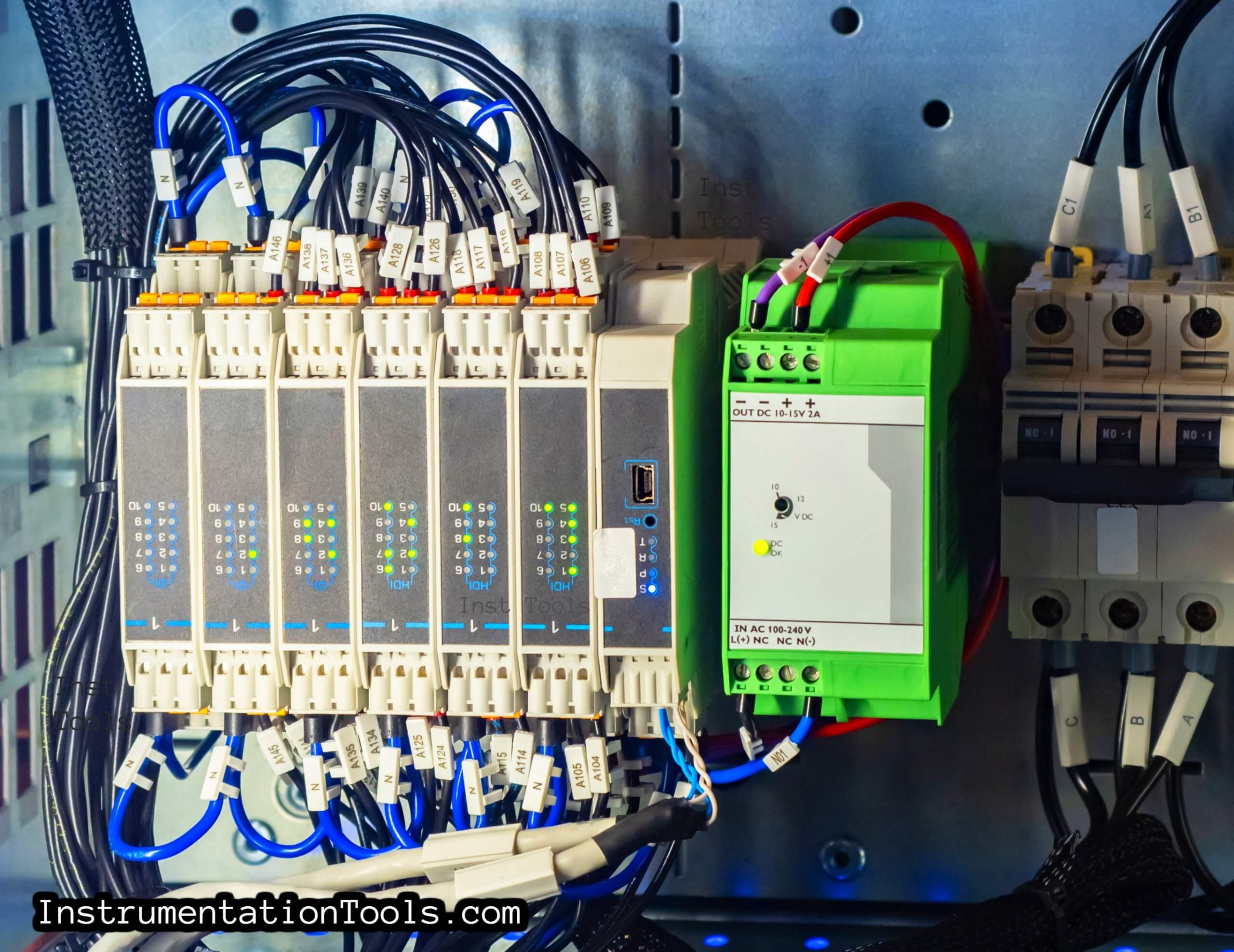
Thank you for the article. The image is not clear.
Thank you for the article. However, I disagree on your interpretation of what the SRS is. It is the Hazard and Risk assessment for a process. The out come of which is the SRS. The SRS is the Safety Requirement Specification for the Instrument Designer and there is a defined separation between Process Safety Engineers and Instrument designers. The SRS should only give safety specifications for the following reasons.
Instrument designers may use a number of methods to achieve the safety system design. Manufacturers can and do change specifications which can be covered by minor MOC. The SRS never changes unless there are changes to process and modifiers. This is the primary Safety Design Document not the Instrument design document. Although both design methodology should be within a design document, within the Safety File, installation , commissioning and verification is separate. Hence FSA 1 verification after design and FSA 2 before introduction of hazards.