Inst ToolsInst ToolsInst Tools
  • Courses
  • Automation
    • PLC
    • Control System
    • Safety System
    • Communication
    • Fire & Gas System
  • Instrumentation
    • Design
    • Pressure
    • Temperature
    • Flow
    • Level
    • Vibration
    • Analyzer
    • Control Valve
    • Switch
    • Calibration
    • Erection & Commissioning
  • Interview
    • Instrumentation
    • Electrical
    • Electronics
    • Practical
  • Q&A
    • Instrumentation
    • Control System
    • Electrical
    • Electronics
    • Analog Electronics
    • Digital Electronics
    • Power Electronics
    • Microprocessor
  • Request
Search
  • Books
  • Software
  • Projects
  • Process
  • Tools
  • Basics
  • Formula
  • Power Plant
  • Root Cause Analysis
  • Electrical Basics
  • Animation
  • Standards
  • 4-20 mA Course
  • Siemens PLC Course
Reading: Resistance in Parallel Circuits
Share
Font ResizerAa
Inst ToolsInst Tools
Font ResizerAa
  • Courses
  • Design
  • PLC
  • Interview
  • Control System
Search
  • Courses
  • Automation
    • PLC
    • Control System
    • Safety System
    • Communication
    • Fire & Gas System
  • Instrumentation
    • Design
    • Pressure
    • Temperature
    • Flow
    • Level
    • Vibration
    • Analyzer
    • Control Valve
    • Switch
    • Calibration
    • Erection & Commissioning
  • Interview
    • Instrumentation
    • Electrical
    • Electronics
    • Practical
  • Q&A
    • Instrumentation
    • Control System
    • Electrical
    • Electronics
    • Analog Electronics
    • Digital Electronics
    • Power Electronics
    • Microprocessor
  • Request
Follow US
All rights reserved. Reproduction in whole or in part without written permission is prohibited.
Inst Tools > Blog > Electrical Theory > Resistance in Parallel Circuits

Resistance in Parallel Circuits

Last updated: July 23, 2018 1:43 pm
Editorial Staff
Electrical Theory
1 Comment
Share
2 Min Read
SHARE

Total resistance in a parallel circuit can be found by applying Ohm’s Law. Divide the voltage across the parallel resistance by the total line current as shown in below equation.

Resistance in Parallel Circuit

Example:

Find the total resistance of the circuit shown in Figure 25 if the line voltage is 120 V and total current is 26A.

Solution :

RT = V/IT

RT = 120 / 26 = 4.62 Ω

The total load connected to a 120 V source is the same as the single “equivalent resistance” of 4.62Ω connected across the source (Figure 26). Equivalent resistance is the total resistance a combination of loads present to a circuit.

Equivalent Resistance in a Parallel Circuit

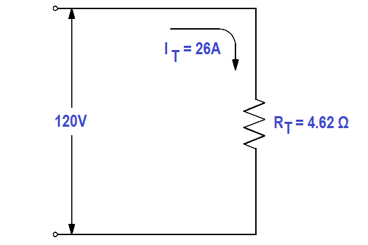
Figure 26 Equivalent Resistance in a Parallel Circuit

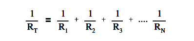
The total resistance in a parallel circuit can also be found by using the below equation.

Total Resistance in a Parallel Circuit Formula

Example 1:

Find the total resistance of a 4Ω, and 8Ω ,and a 16Ω resistor in parallel (Figure 27).

Total Resistance in a Parallel Circuit

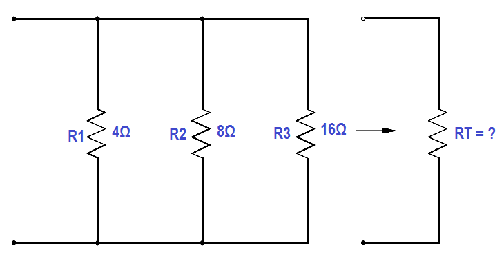
Figure 27 Total Resistance in a Parallel Circuit

Solution :

Total Resistance in a Parallel Circuit Formula

1 / RT = 1/4 + 1/8 + 1/16

RT = 16/7 = 2.29 Ω

Note: Whenever resistors are in parallel, the total resistance is always smaller than any single branch.

Example 2:

Now add a fourth resistance of 4Ω in parallel to the circuit in Figure 27. What is the new total resistance of the circuit?

Solution:

Total Resistance in a Parallel Circuit Formula

1 / RT = 1/4 + 1/8 + 1/16 + 1/4

RT = 16/11 = 1.45 Ω

Don't Miss Our Updates
Be the first to get exclusive content straight to your email.
We promise not to spam you. You can unsubscribe at any time.
Invalid email address
You've successfully subscribed !

Continue Reading

Units of Electrical Measurement
Block Diagram
Wiring Diagram
Series-Wound DC Generators
Electrical Symbols
Series – Parallel Circuit Analysis
Share This Article
Facebook Whatsapp Whatsapp LinkedIn Copy Link
Share
1 Comment
  • Daniel Hynes says:
    March 25, 2021 at 7:40 pm

    confused? how do you find the dividing number? base number to dived into the highest resistance total?

    Reply

Leave a Reply Cancel reply

Your email address will not be published. Required fields are marked *

Stay Connected

128.3kFollowersLike
69.1kFollowersFollow
210kSubscribersSubscribe
38kFollowersFollow

Categories

Explore More

Parallel AC Generators
Classification of Transformers
Power Factor
Applying Kirchhoff’s Current Law
Y and Delta Resistor Network Calculations
Induction Motor Torque Versus Slip
Three Phase Transformer Connections
Current Division

Keep Learning

Series - Wound DC Motor

Series-Wound Motor

AC Generator Operation

Types of AC Generators

Capacitors Connected in Parallel

Series and Parallel Capacitors

Parallel RLC Circuit

Resonance, Resonant Frequency, Series and Parallel Resonance

Marking Polarity

DC Circuit Analysis Loop Equations

Left-hand Rule for Current Carrying Conductors

Magnetism

Parallel Circuit

Parallel Circuit

Motor Rotating Magnetic Field

AC Motor Theory

Learn More

Electrical & Instrumentation QA QC Interview Questions

100 Electrical & Instrumentation QA QC Interview Questions

Vibration Analysis

Top 100 Vibration Analysis Questions and Answers

Why do we need to Control the Motion using VFD drives

Why do we need to Control the Motion using VFD drives?

Seven Segment LED Display

Difference Between Common Cathode and Common Anode 7 Segment LED Display?

Electrical Machines Objective Questions

Electrical Machines MCQ Series 19

Multi-Cartridge Filter

Cartridge Filters

Thermocouple Extension Lead Minimizer Circuit

Thermocouple Wires and Extension Lead Issues

Industrial Automation Components

Industrial Automation Components Questions and Answers

Menu

  • About
  • Privacy Policy
  • Copyright

Quick Links

  • Learn PLC
  • Helping Hand
  • Part Time Job

YouTube Subscribe

Follow US
All rights reserved. Reproduction in whole or in part without written permission is prohibited.
Welcome Back!

Sign in to your account

Username or Email Address
Password

Lost your password?