A Real-Time Clock calculates the time (ranging from seconds to years) accurately and stores the data in real-time. The results of the time calculation process performed by the RTC will be stored or sent to other devices through the interface system. RTC aims to provide an accurate date and time even when the system is down.
Real-Time Clock
Real-time clock (RTC) typically consists of various electronic components, such as highly stable oscillator crystals, and backup power sources such as batteries or capacitors. This backup power source allows the RTC to continue running and keep time even when the primary device shuts down or loses power during emergencies
Uses of RTC
- Real-time Time Monitoring
- Logging and Timestamping
- Alarm System
- Power Management
Real-Time Clock in OMRON PLC
RTC (Real Time Clock) in CX-Programmer Software is used as a provider of time functions ranging from units of Seconds, Minutes, Hours, Dates, Months, Years, and Day sequences.
RTC can be used as an alarm function that can work periodically or only at one particular time. RTC (Real Time Clock) data allocation in CX-Programmer Software is stored in memory area A (Auxiliary) at addresses A351 to A354, see figure below.
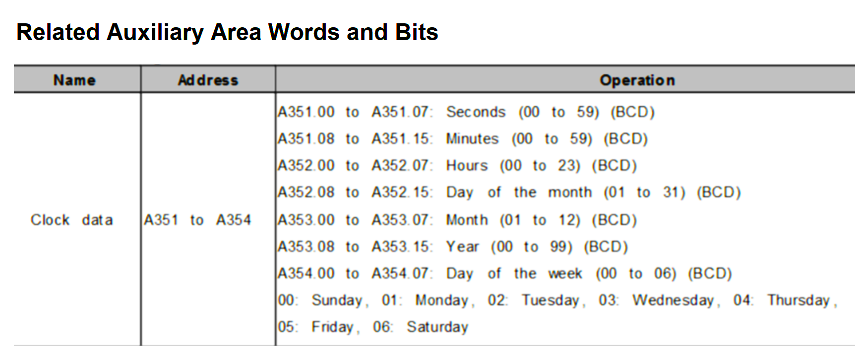
RTC Addressing in CX-Programmer
| Word Memory Area | Bit Area | Function | Range Time | Data Type |
| A351 | A351.00 – A351.07 | Seconds | 00 – 59 | BCD |
| A351.08 – A351.15 | Minutes | 00 – 59 | BCD | |
| A352 | A352.00 – A352.07 | Hours | 00 – 23 | BCD |
| A352.08 – A351.15 | Date | 0 – 31 | BCD | |
| A353 | A353.00 – A353.07 | Month | 01 – 12 | BCD |
| A353.08 – A353.15 | Year | 00 – 99 | BCD | |
| A354 | A354.00 – A354.07 | Day of the Week | 00 – 06 | BCD |
| Not used |
In Figures and Tables, it is explained that each Memory Word data allocation is used for 2 units of time which are processed in the form of BCD (Binary Code Decimal) units.
Please also note, that RTC (Real Time Clock) readings can only be displayed in HEXADECIMAL number units. In the data allocation, A354 (Day of the Week) serves to express the order of days in one week.
The sequence is as follows :
00: Sunday
01: Monday
02: Tuesday
03: Wednesday
04: Thursday
05: Friday
06: Saturday
Not all types of OMRON PLCs have the RTC (Real Time Clock) function.
How to Use Real-Time Clock in CX-Programmer?
Open CX-Programmer Software, and select the type of PLC that supports the use of RTC (Real Time Clock).
Step-One
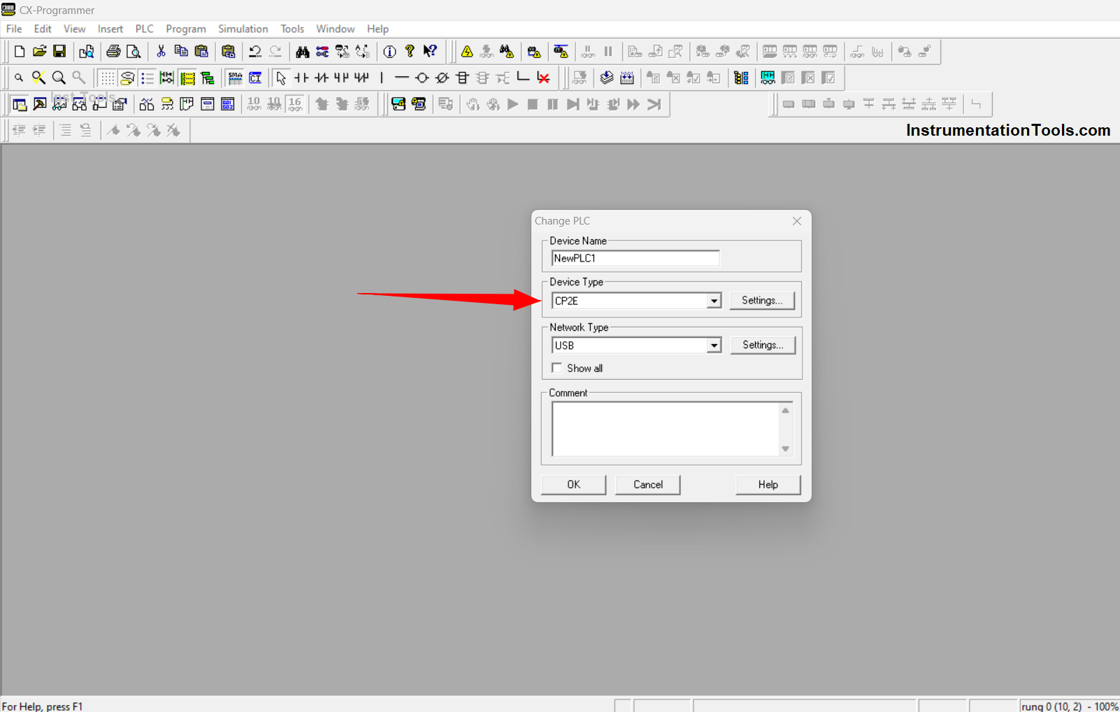
In this example, using OMRON PLC type CP2E. after selecting PLC Type Click “OK” to get into the worksheet page.
Step-Two
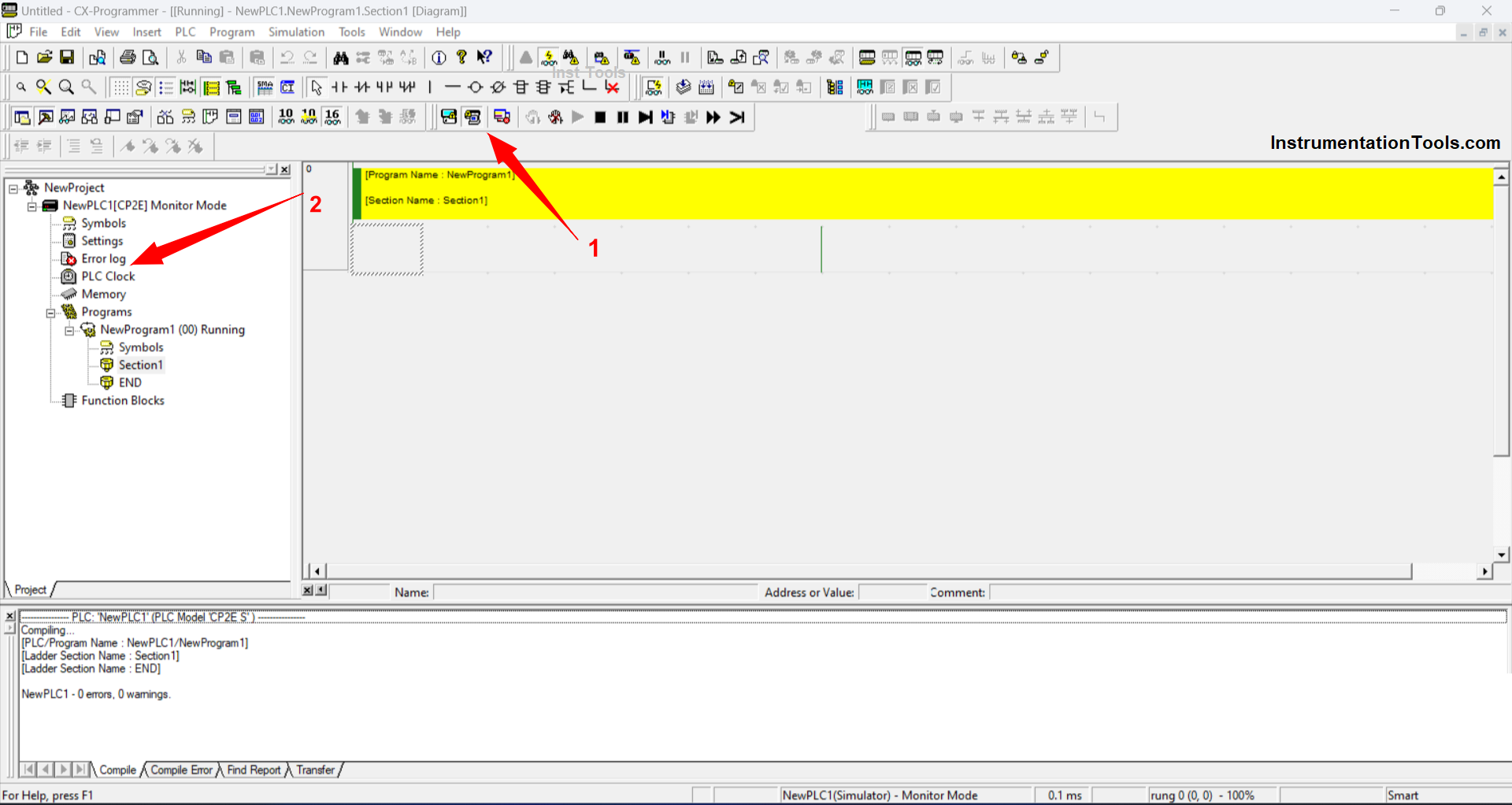
Because this example of the RTC (Real Time Clock) Program is done by simulation, then click activate the Work Online Simulator function (see arrow no.1) or use the shortcut “CTRL+Shift+W)” to START Online Simulation mode.
After the Online Simulation mode is active, the “PLC Clock” Sub-Function will appear, click the Sub-Function to view and set the parameters.
Step-Three
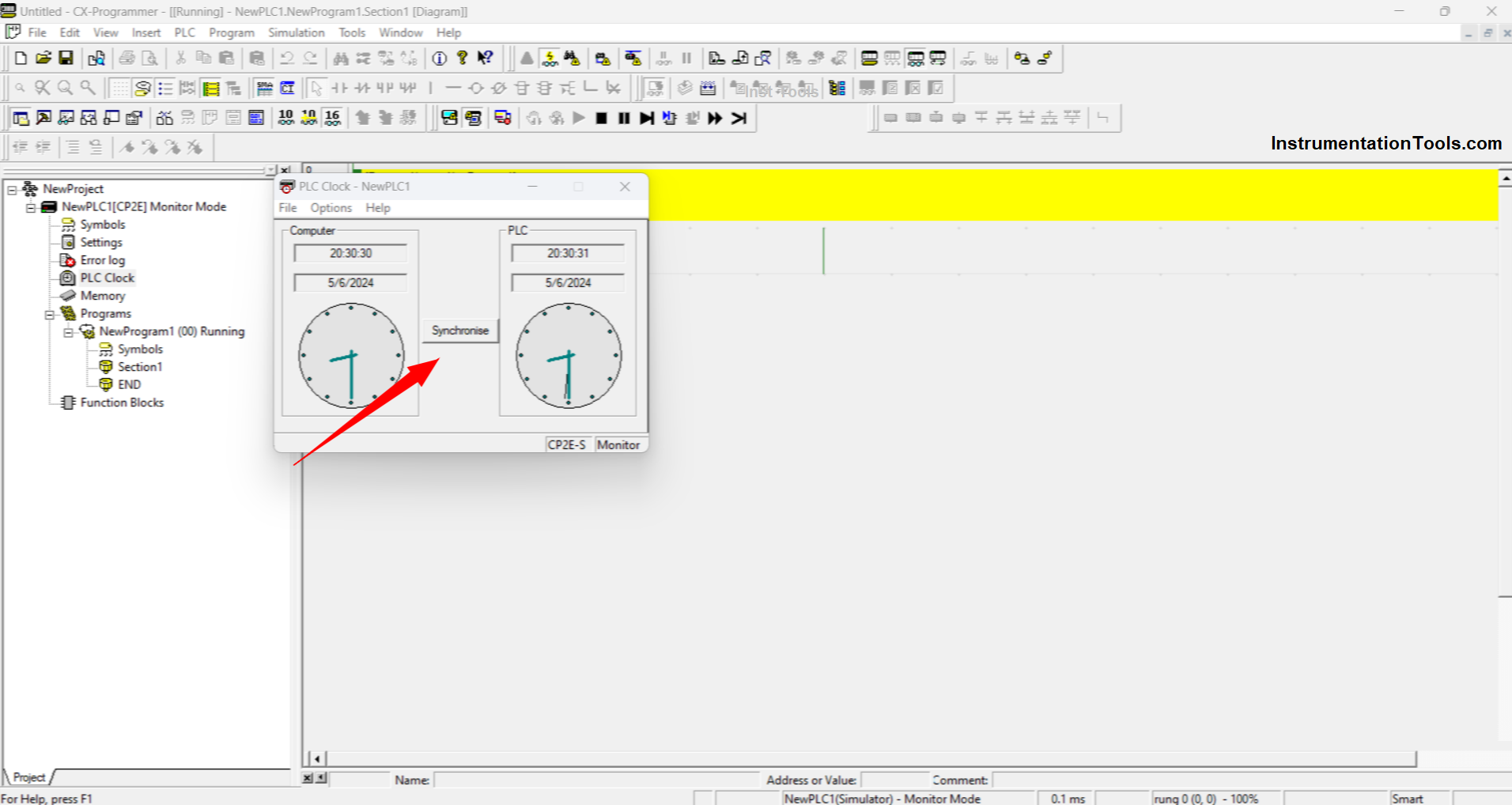
A new Pop-Up menu will appear that displays the time on the Computer / PC and on the PLC. Time conditions on the Computer / PC and the PLC can be different because the time settings in the PLC or on the PC can change.
To synchronize the PLC time to match the time on the Computer/PC click “Synchronise”.
Step-Four
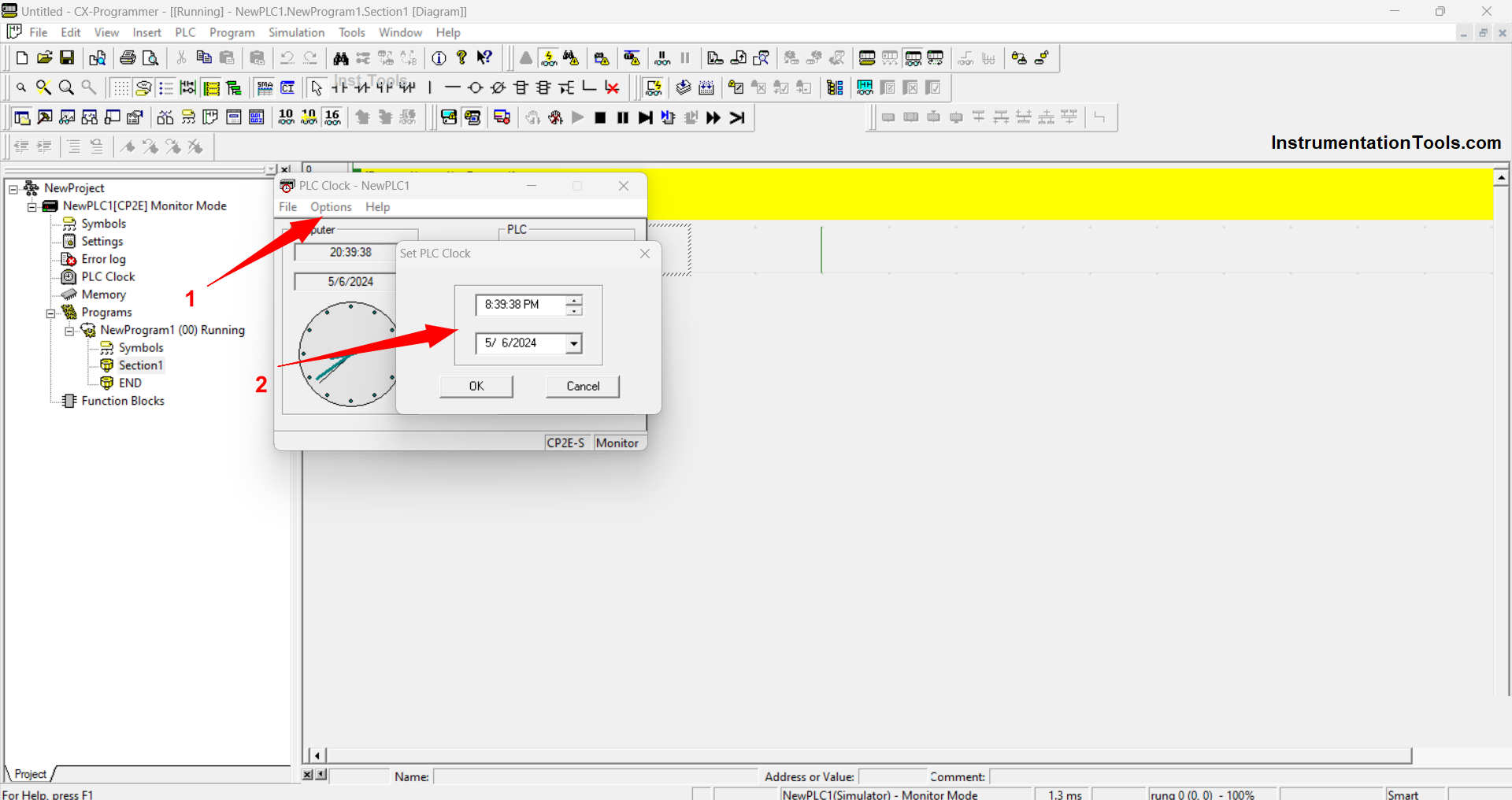
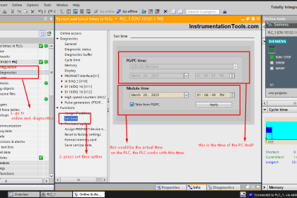
To set the time on the PLC, click “Option” on the PLC Clock Pop-Up menu then select “Set PLC Clock” Then a new Pop-Up will appear that can be used to set time parameters from Seconds to Years.
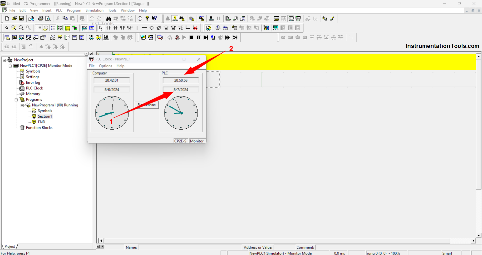
The picture above is the result of setting the time parameters that have been done, it can be seen that the time “Minutes” and “Months” on the PLC is different from the time on the Computer / PC. If you want to sync it again, click the “Synchronise” icon.
Step-Five
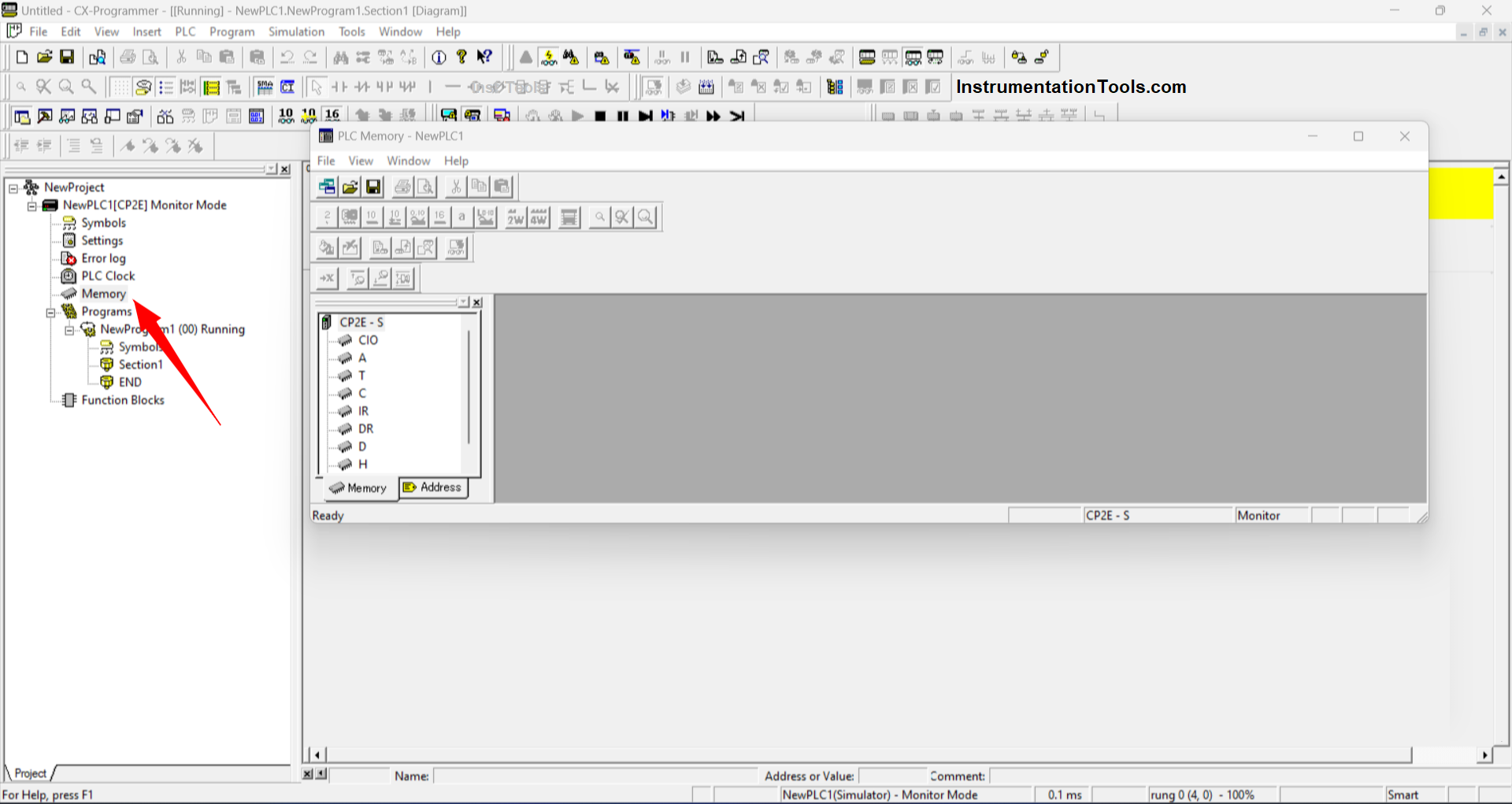
Click the “Memory” Sub-Function to see the RTC (Real Time Clock) working process on memory allocation. Then a new worksheet will appear that functions to monitor and manage data on each memory allocation.
Click memory allocation A “Auxiliary” because RTC data processing on PLC OMRON works on memory allocation A “Auxiliary” at address “A351-A354”.
Then click the Monitor function icon (arrow no.2) then a Pop-Up will appear named “Monitor Memory Areas”. Click “Monitor” on the pop-up that appears to activate Area Memory Monitor mode.
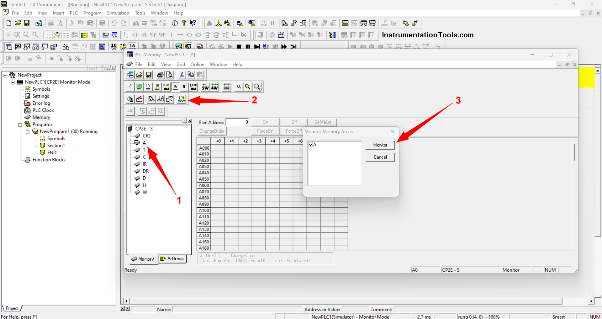
In the “Area Memory Monitor” mode condition, a value will appear in each memory data allocation.
In the memory address area, A351 to A354 will appear as a value/number that is the same as the time on the Computer / PC (with a note of the PLC and Computer / PC synchronous time setting conditions).
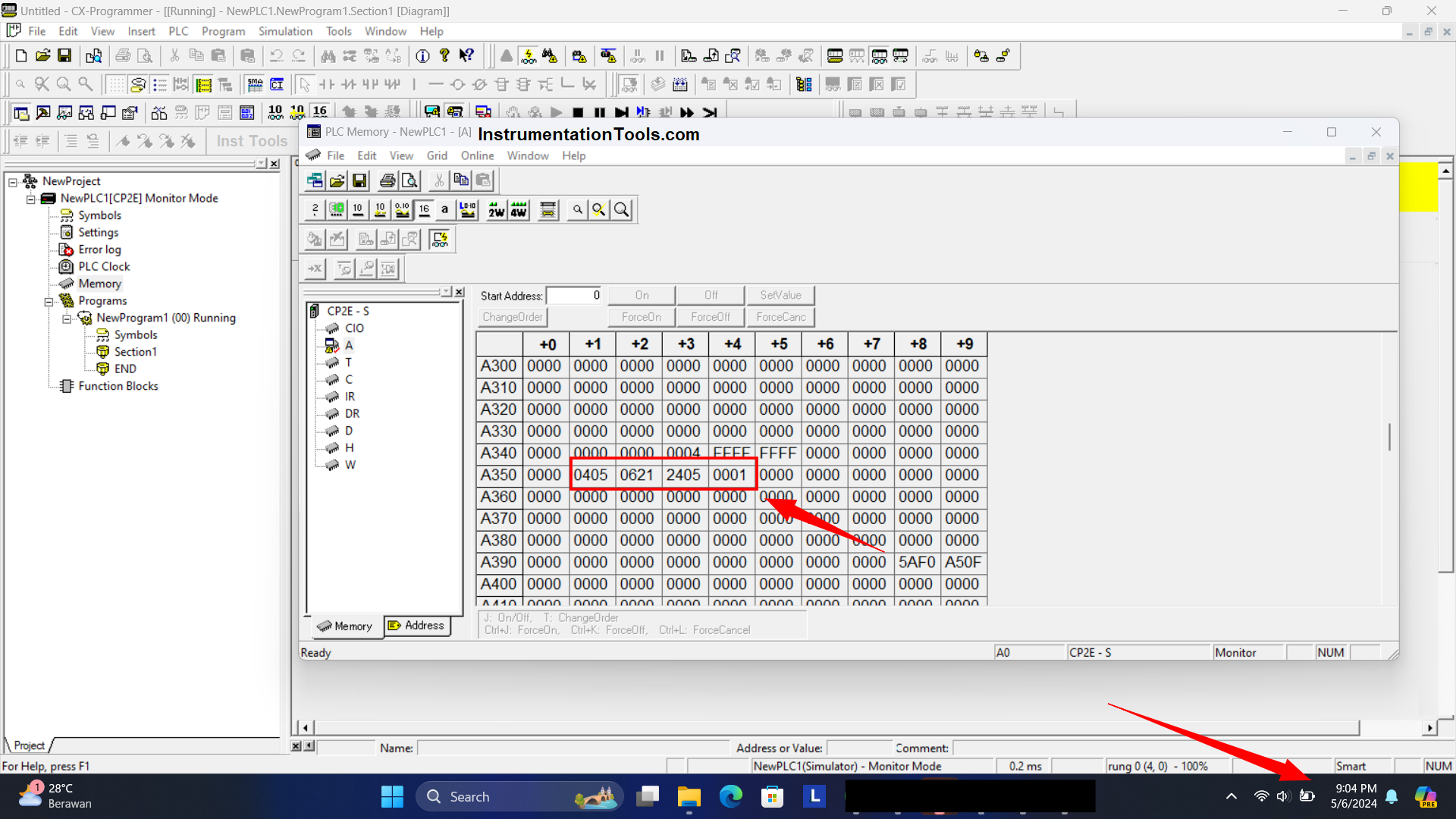
In memory area A351 states the time “Minute 04 and Seconds 05”, memory area A352 states the time “Date 06 and 21 o’clock”.
Memory area A353 states the time “Year 24 (2024) and Month 06”, and in memory allocation A354 states time “Order of day 01 = Monday”.
Step-Six
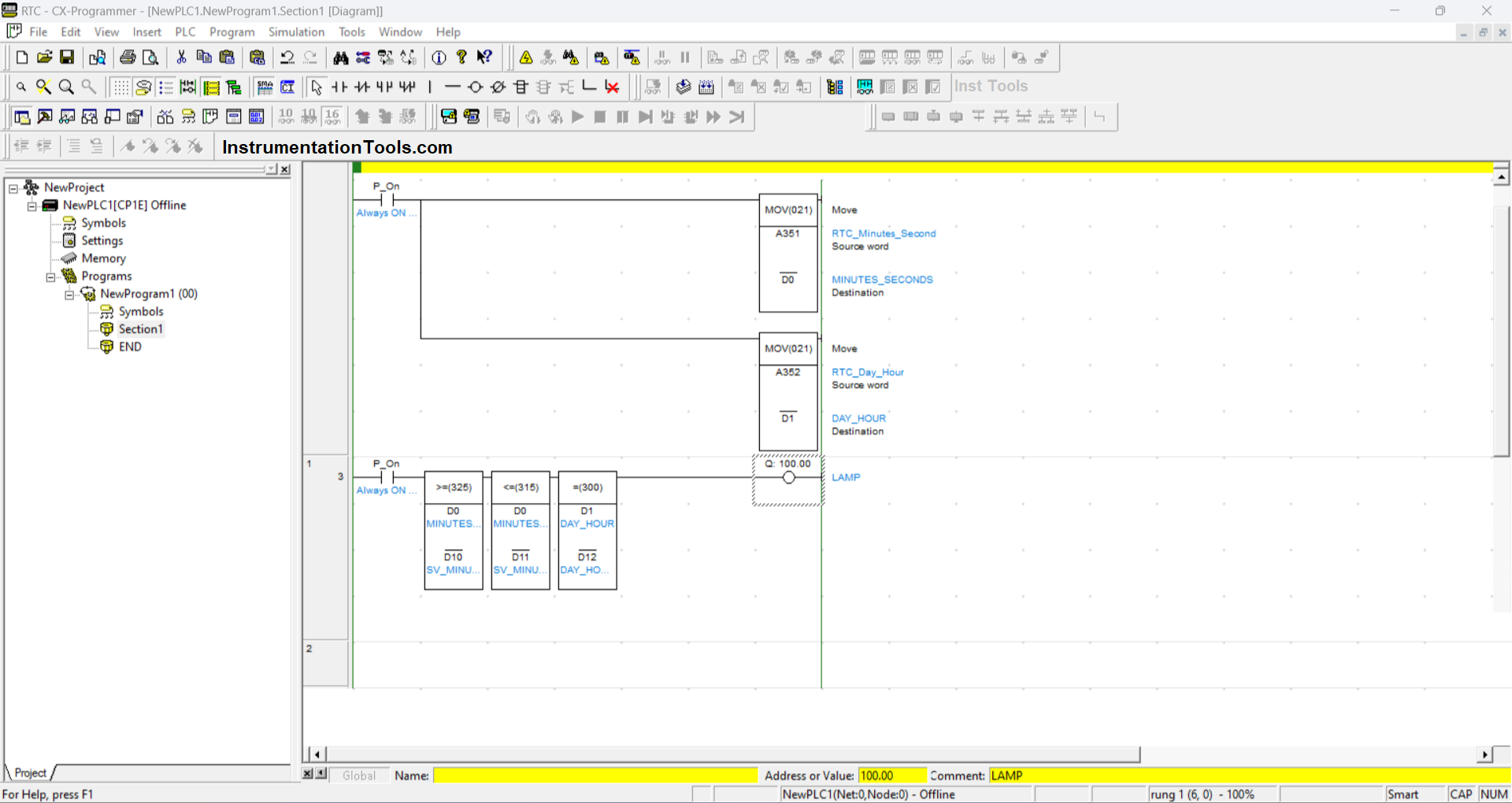
Time data from RTC can be used or processed for timing needs in the PLC Program. The program in the picture above serves to turn ON and OFF the LAMP Output contact (100.00) at a certain period.
RTC “Minutes and Seconds” data from A351 memory allocation will be moved to memory address “D0” using “MOV” Instruction and RTC “Date and Time” data from A352 memory allocation will be moved to memory address “D1”. Time data that has been transferred to memory allocations “D0” and “D1” will be processed using Instruction Comparison Data.
Instruction “325” (Greater than or equal to) compares the “D0” data containing the “Minutes and Seconds” of the RTC with the “Set Value” data filled in the address “D10”, so that if the data of “D0” is greater than or equal to the data of “D10” then the Instruction will be ACTIVE.
Instruction “315” (Less than or equal to) compares the “D0” data containing Minutes and Seconds from the RTC with the “Set Value” data filled in the address “D11” so that if the data from “D0” is less than or equal to the “D11” data then the Instruction will be ACTIVE and when the “D0” data is greater than “D11” then the instruction “315”/Less than or equal to” will be OFF.
Instruction “300” (Equal) compares the “D1” data containing “Date and Time” with the “Set Value” data filled in the memory address “D12”.
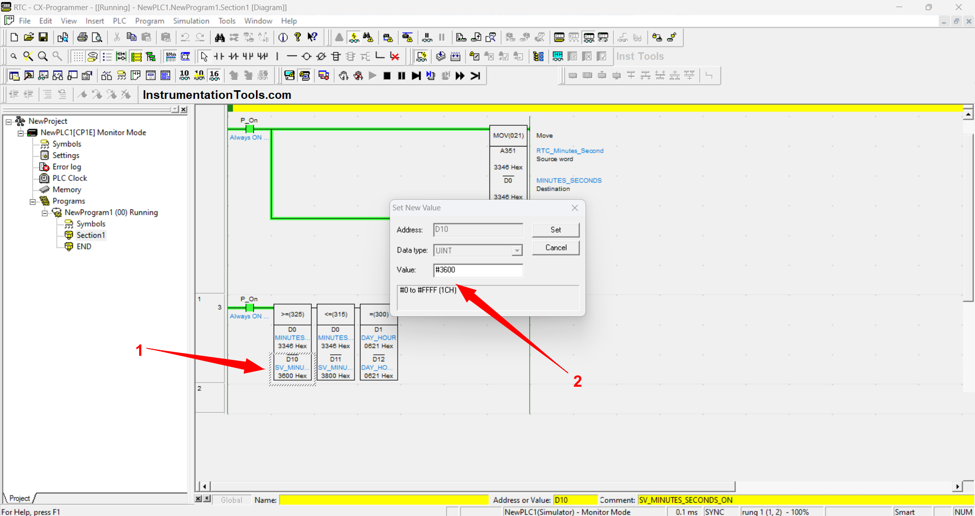
When the PLC Program is RUN or simulated we can enter the value “Set value” to the memory address “D10, D11, D12” by clicking on the memory allocation in the Instruction.
The entered value must be preceded by the addition of the “#” format because the data entered must be in “Binary” units.
In the simulation picture above, the value of “Set Value” has been set at the memory address “D0 = 3600” which means when the time is valued at “Minute 36 Seconds 00” then Instruction “325” will be ACTIVE, at the address “D11 = 3800” which means when the time value is less than or before “Minute 38 Seconds 00”.
Then Instruction “315” will be ACTIVE and when the value of “D0” exceeds “Minute 38 Seconds 00” then Instruction “315” will be DISABLED. At the address ENTER the value “D12 = 0621″ which means when ”06 o’clock 21″ then instruction “300” will be ACTIVE.
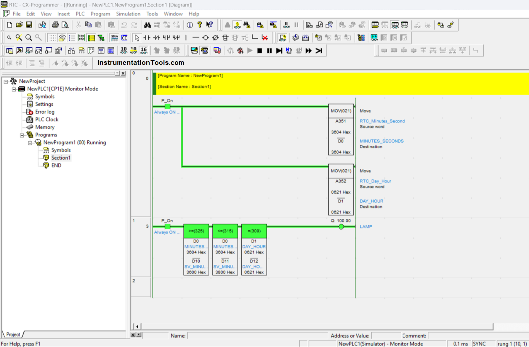
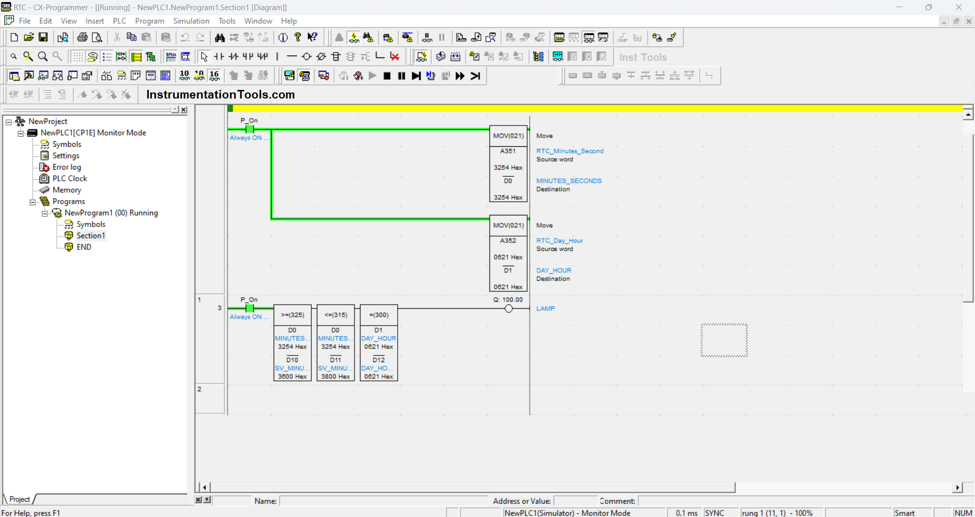
The above condition is when all Instruction conditions are met resulting in the LAMP Output contact (100.00) ACTIVE.
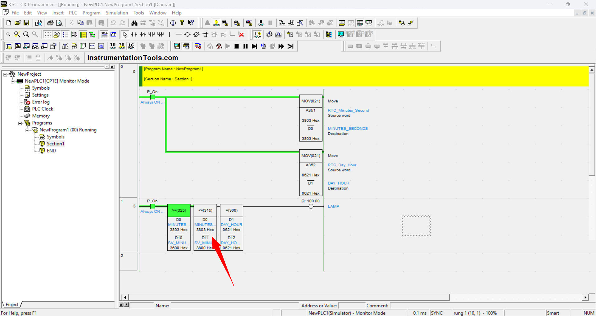
In this condition Instruction “315” has been DISABLED because the desired condition of the Instruction has passed, i.e. the value of “D0” becomes greater than the value of “D12”, so that the Output contact (100.00) becomes DISABLED.
If you liked this article, please subscribe to our YouTube Channel for PLC and SCADA video tutorials.
You can also follow us on Facebook and Twitter to receive daily updates.
Read Next:
- Free Omron PLC Programming Course
- PLC and MCC Panel Interface Signals
- PLC Control 3 Motors with Switch
- Shutter Door Control using Motor
- VFD Simulator Software Download