Inst ToolsInst ToolsInst Tools
  • Courses
  • Automation
    • PLC
    • Control System
    • Safety System
    • Communication
    • Fire & Gas System
  • Instrumentation
    • Design
    • Pressure
    • Temperature
    • Flow
    • Level
    • Vibration
    • Analyzer
    • Control Valve
    • Switch
    • Calibration
    • Erection & Commissioning
  • Interview
    • Instrumentation
    • Electrical
    • Electronics
    • Practical
  • Q&A
    • Instrumentation
    • Control System
    • Electrical
    • Electronics
    • Analog Electronics
    • Digital Electronics
    • Power Electronics
    • Microprocessor
  • Request
Search
  • Books
  • Software
  • Projects
  • Process
  • Tools
  • Basics
  • Formula
  • Power Plant
  • Root Cause Analysis
  • Electrical Basics
  • Animation
  • Standards
  • 4-20 mA Course
  • Siemens PLC Course
Reading: Quiz Program Logic Using PLC Programming
Share
Font ResizerAa
Inst ToolsInst Tools
Font ResizerAa
  • Courses
  • Design
  • PLC
  • Interview
  • Control System
Search
  • Courses
  • Automation
    • PLC
    • Control System
    • Safety System
    • Communication
    • Fire & Gas System
  • Instrumentation
    • Design
    • Pressure
    • Temperature
    • Flow
    • Level
    • Vibration
    • Analyzer
    • Control Valve
    • Switch
    • Calibration
    • Erection & Commissioning
  • Interview
    • Instrumentation
    • Electrical
    • Electronics
    • Practical
  • Q&A
    • Instrumentation
    • Control System
    • Electrical
    • Electronics
    • Analog Electronics
    • Digital Electronics
    • Power Electronics
    • Microprocessor
  • Request
Follow US
All rights reserved. Reproduction in whole or in part without written permission is prohibited.
Inst Tools > Blog > PLC Tutorials > Quiz Program Logic Using PLC Programming

Quiz Program Logic Using PLC Programming

Last updated: March 4, 2021 3:44 pm
Editorial Staff
PLC Tutorials
No Comments
Share
3 Min Read
SHARE

Build the ladder logic program to satisfy the condition for Quiz program logic.

Contents
PLC Quiz ProgramList of Inputs and OutputsPLC ProgrammingLadder Logic DescriptionConclusion:

PLC Quiz Program

PLC Quiz Project

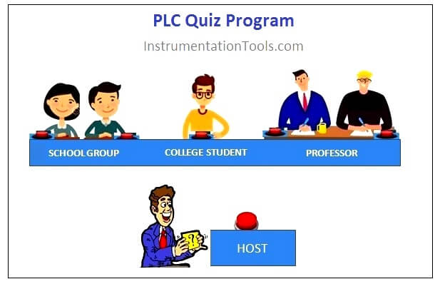
There are three groups participating in quiz program. Since the people are from different age group, host is planning to give more concern/preference in pressing buzzer to smaller age group.

Any one person from School group pressed buzzer is taken as first IN input, College group is having no option and the professor group should press both buzzer at same time to check in as First IN input. Host buzzer is to reset all outputs (Lamp)

Consider,

School group buzzer named as A0, A1 and Lamp as X0

College Group buzzer named as A2 and Lamp as X1

Professor group buzzer named as A3, A4 and Lamp as X2

Host Buzzer named as A5

X0 should ON if any one of A0 or A1 is pressed.

X1 should ON when A2 is pressed

X2 should ON when both A3 and A4 are pressed

If A5 is pressed, X0, X1 and X2 should OFF.

List of Inputs and Outputs
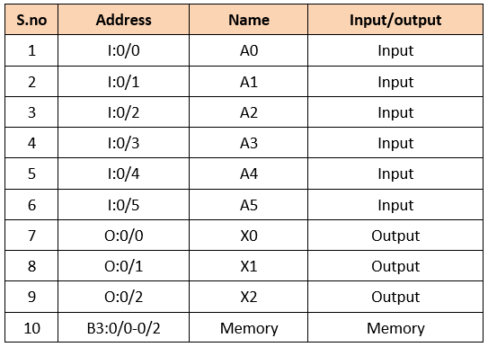
PLC Quiz Program Inputs and Outputs

PLC Programming

Quiz Program Logic Using PLC Programming
Quiz Project Using PLC Ladder Logic

Ladder Logic Description

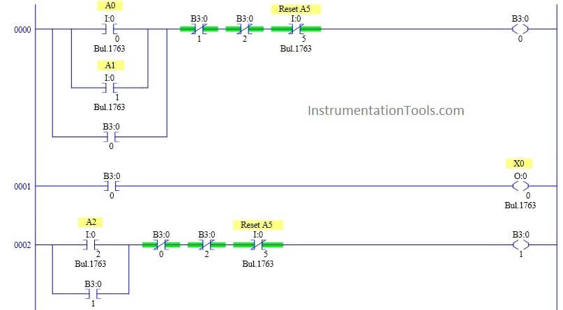
RUNG 0000

School group buzzers PB  are connected in parallel to give either option. Since buzzer is push button, latching is performed using memory coil.

Reset input is connected as normally closed switch in series to reset the output.B3:0/1 and B3:0/2 are connected as normally closed switch in series to interlock the output.

RUNG 0001

To make the condition possible, previous rung output B3:0/0  is connected to school group lamp X0.

RUNG 0002

College group buzzer PB is connected to memory coil with normally closed switch in series to reset the output. B3:0/0 and B3:0/2 are connected as normally closed switch in series to interlock the output.

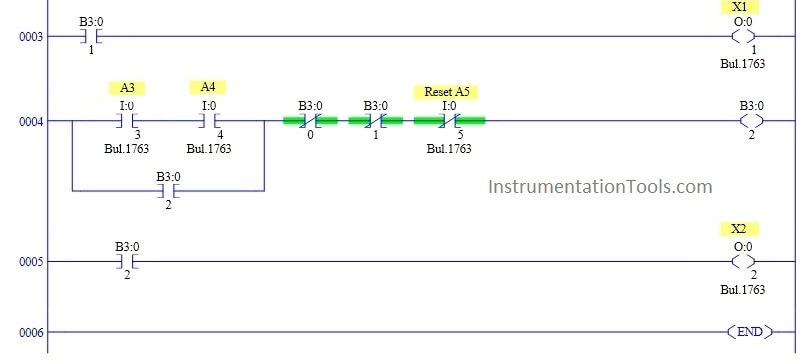
RUNG 0003

To make the condition possible, previous rung output B3:0/1 is connected to college group lamp X1.

RUNG 0004

For Professor group, both the buzzer PBs are  connected in series to memory coil with normally closed switch in series to reset the output. B3:0/0 and B3:0/1 are connected as normally closed switch in series to interlock the output.

RUNG 0005

To make the condition possible, previous rung output B3:0/2 is connected to Professor Group lamp X2.

Conclusion:

The above explained ladder logic for quiz program is for example only. We can use this example program to understand the working of Push Buttons, memory bit and Interlocking in AB PLC.

Author : Hema Sundaresan

If you liked this article, then please subscribe to our YouTube Channel for PLC and SCADA video tutorials.

You can also follow us on Facebook and Twitter to receive daily updates.

Read Next:
Electromagnetic Relay

PLC Output Types

PLC Latching Function

Relay Loop Back Circuit

PLC Ladder Diagrams

Don't Miss Our Updates
Be the first to get exclusive content straight to your email.
We promise not to spam you. You can unsubscribe at any time.
Invalid email address
You've successfully subscribed !

Continue Reading

Types of Interrupt OB in Siemens Tia Portal
Interconnection between PLC, MCC, LCP & Pumps – Video
Siemens PLC Mathematics Instructions
PLC Motor Control Ladder Logic Programming
What are Analog and Digital Signals? Differences, Examples
How to choose between PLC and DCS Systems ?
Share This Article
Facebook Whatsapp Whatsapp LinkedIn Copy Link
Share
Leave a Comment

Leave a Reply Cancel reply

Your email address will not be published. Required fields are marked *

Stay Connected

128.3kFollowersLike
69.1kFollowersFollow
210kSubscribersSubscribe
38kFollowersFollow

Categories

Explore More

Function Block (FB) for Motor Control Logic
Dosing Pump PLC Logic
Retentive ON Delay Timer using PLC
PLC Programming Example on LED Control
Remote Factory Acceptance Test
Structured Text vs. Instruction List for PLC Programming
PLC Program for Blinking Lamp on 5 Seconds Interval
Top Automation Vendors from Around the World – An Overview

Keep Learning

PLC SCADA Water Pump

PLC Program for Controlling a Water Pump with 3 Power Sources

OMRON PLC program for waste-burning automation

Waste-Burning System OMRON PLC Program Example

Free Schneider PLC Training - Automation Course

Free Schneider PLC Training – Automation Course

PLC Program for Sequential Motor Control

PLC Program for Sequential Motor Control

Creating Logic in Intouch Using Scripting

Create Logic with InTouch Scada using Scripting

Firmware Version in Siemens PLC

What is the Firmware Version of a PLC? – Siemens PLC Hardware

PLC Program for Fish Feeding System

PLC Program for Fish Feeding System

How to set password in Siemens HMI

How to Password Protect HMI in Siemens TIA Portal?

Learn More

Faceplate in WinCC

Siemens HMI Training – Using UDTs with Faceplates

Analog Electronics Projects

Analog Electronic Projects for Final Year Engineering Students

Power Supply Unit with Diode Protection

Why we use Diode Protection Modules ?

Micro 870 Rockwell PLC

Rockwell Automation Allen Bradley PLC for Smaller and Medium Projects

SIS Application Program - Safety Instrumented System

SIS Application Program – Safety Instrumented System

Wiring Diagram

Wiring Diagram

Control Panels Material Take-Off (MTO)

Control Panels Material Take-Off (MTO) – Engineering Project

Non-Contacting-Radar-Level-Transmitter-Animation

Non Contacting Radar Level Transmitter Animation

Menu

  • About
  • Privacy Policy
  • Copyright

Quick Links

  • Learn PLC
  • Helping Hand
  • Part Time Job

YouTube Subscribe

Follow US
All rights reserved. Reproduction in whole or in part without written permission is prohibited.
Welcome Back!

Sign in to your account

Username or Email Address
Password

Lost your password?