Inst ToolsInst ToolsInst Tools
  • Ask
  • Courses
  • Videos
  • Q & A
    • Interview
      • Instrumentation
      • Electronics
      • Electrical
      • Practical Questions
    • MCQ
      • Instrumentation MCQ
      • Electrical MCQ
      • Electronics MCQ
      • Control Systems MCQ
      • Analog Electronics MCQ
      • Digital Electronics MCQ
      • Power Electronics MCQ
      • Microprocessor MCQ
      • Multiple Choice Questions
  • EE
    • Electronics
      • Electronics Q & A
      • Electronic Basics
      • Electronic Devices & Circuits
      • Electronics Animation
      • Digital Electronics
    • Electrical
      • Electrical Basics
      • Electrical Q & A
      • Power Electronics
      • Electrical Machines
      • Electrical Animation
      • Power Systems
      • Switchgear & Protection
      • Transmission & Distribution
  • Measure
    • Control Valves
    • Calibration
    • Temperature
    • Pressure
    • Flow
    • Level
    • Analyzers
    • Switches
    • Vibration
    • Solenoid Valve
  • Control
    • PLC Tutorials
    • Control Systems
    • Safety Instrumented System (SIS)
    • Communication
    • Fire & Gas System
  • More
    • Design
    • Tools
    • Animation
    • Basics
    • Formulas
    • Standards
    • TextBooks
    • Common
    • Software
    • Excel Tools
    • Erection & Commissioning
    • Process Fundamentals
    • Videos
    • Books
Search
All rights reserved. Reproduction in whole or in part without written permission is prohibited.
Reading: Questions on DP Transmitter Wet Leg Compensating Impulse Line
Share
Notification Show More
Font ResizerAa
Inst ToolsInst Tools
Font ResizerAa
  • Courses
  • PLC Tutorials
  • Control Systems
Search
  • Ask
  • Courses
  • Videos
  • Q & A
    • Interview
    • MCQ
  • EE
    • Electronics
    • Electrical
  • Measure
    • Control Valves
    • Calibration
    • Temperature
    • Pressure
    • Flow
    • Level
    • Analyzers
    • Switches
    • Vibration
    • Solenoid Valve
  • Control
    • PLC Tutorials
    • Control Systems
    • Safety Instrumented System (SIS)
    • Communication
    • Fire & Gas System
  • More
    • Design
    • Tools
    • Animation
    • Basics
    • Formulas
    • Standards
    • TextBooks
    • Common
    • Software
    • Excel Tools
    • Erection & Commissioning
    • Process Fundamentals
    • Videos
    • Books
Follow US
All rights reserved. Reproduction in whole or in part without written permission is prohibited.
Inst Tools > Blog > Practical Questions > Questions on DP Transmitter Wet Leg Compensating Impulse Line

Questions on DP Transmitter Wet Leg Compensating Impulse Line

Calculate the appropriate LRV and URV pressures for the DP Transmitter with Wet Leg Compensating Impulse Line.

Last updated: January 19, 2021 8:44 pm
Editorial Staff
Practical Questions
3 Comments
Share
2 Min Read
SHARE

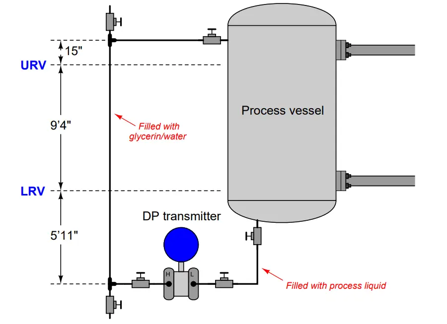
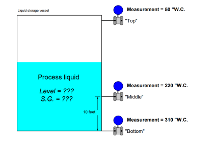
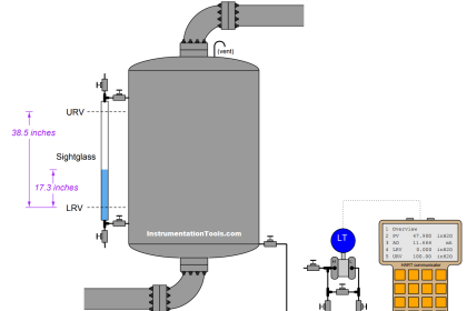
Calculate the appropriate LRV and URV pressures for this hydrostatic level measurement system.

Assuming the process liquid has a weight density of 44 pounds per cubic foot at a temperature of 23 degrees Celsius, and that the “wet leg” compensating impulse line is filled with a glycerin/water mix (S.G. = 1.13).

Assume a static vessel pressure of 126 PSI:

Questions on DP Transmitter Wet Leg Compensating Impulse Line

Question 1:

Express your answers in units of inches water column (”W.C. or ”H2O).

Answer:

LRV = +173.7 ”H2O

URV = +94.76 ”H2O

The temperature and static pressure values are extraneous information, included for the purpose of challenging students to identify whether or not information is relevant to solving a particular problem.

Question 2:

As liquid level increases in this vessel, will the transmitter’s signal increase or decrease (i.e. is this level transmitter direct or reverse acting?

Question 3:

If the process liquid heats up and becomes less dense (but the actual level remains the same), will the transmitter’s 4-20 mA signal increase, decrease, or remain the same?

Question 4:

If the wet leg is filled with pure glycerin instead of a glycerin/water mixture (but the process liquid level remains the same), will the transmitter’s 4-20 mA signal increase, decrease, or remain the same?

Question 5:

How would this system respond if someone closed the upper nozzle block valve, isolating the compensating leg impulse line from the process vessel?

Question 6:

Describe a step-by-step procedure for re-filling the wet leg with glycerin, assuming a pressurized vessel.

Do you find any mistake in these questions?

Share with us through below comments section.

Read Next:

  • Transmitters Compensated Leg Systems
  • Level Measurement with Wet leg
  • Density Measurement using DP Transmitter
  • Rate Compensated Heat Detectors Working Principle
  • Closed tank DP Level Transmitter Calibration

Credits: Tony Kuphaldt

Don't Miss Our Updates
Be the first to get exclusive content straight to your email.
We promise not to spam you. You can unsubscribe at any time.
Invalid email address
You've successfully subscribed !
Practical Process Control System Questions & Answers – 2
How much Pressure is applied to Inclined Water Manometer?
Determine the functions of Pressure Switches ?
Solenoid Valves Questions & Answers – 3
Calculate Density and Specific Gravity
Share This Article
Facebook Whatsapp Whatsapp LinkedIn Copy Link
Share
3 Comments
  • hayder azeez says:
    January 19, 2021 at 10:42 pm

    Answer2: decrease
    Answer3:remain the same
    Answer4:remain the same
    Answer5: signal is stay constant with last case before close nozzle
    Answer6:
    The column will be affected by the pressure of the tank, whether it is an increase or decrease, and thus the reading of the transmitter will change if there is a change in the liquid level
    All that by imposing a closed air pressure equalization valve

    -I hope I understand the questions well

    best regards

    Reply
  • Ahmed says:
    January 27, 2021 at 7:25 pm

    How possible the low side of the DP be connected to the bottom of the Process VESSEL.

    Answer for URV and LRV for the above question is not correct , I’ve got (LRV = -206.79” H2O, URV= -128.79 )

    Formula I used

    LRV= Lmin * SGp – (H1+H2) * SGf

    URV= Lmax* SGp – (H1+H2) * SGf

    Reply
  • Avi dadon says:
    June 30, 2022 at 7:56 pm

    Answer 1: URV = +94.76 ”H2O , LRV = +173.7 ”H2O

    Answer 2: As liquid level increases in this vessel, the transmitter’s signal
    increases.

    Answer 3: If the process liquid heats up and becomes less dense (but the actual
    level remains the same),the differential pressure increase there by the
    transmitter’s 4-20 mA signal decrease.

    Answer 4: If the wet leg is filled with pure glycerin (s.g=1.26) instead of a
    glycerin/water mixture (s.g=1.13) (but the process liquid level remains
    the same),the differential pressure increase there by the
    transmitter’s 4-20 mA signal decrease.

    Answer 5: If the static pressure (vapor pressure) in the vessel will not change the
    readings before closing the valve will remain the same.
    If the static pressure increase (above 126 psi) then the differential
    pressure will decrease and there for the transmitter reading will increase
    (there by level readings will increase also).
    If the static pressure decrease (less then 126 psi) then the differential
    pressure will increase and there for the transmitter reading will decrease
    (there by level readings will decrease also).

    Answer 6: procedure for re-filling the wet leg with glycerin:
    step 0: make sure bypass valve on the transmitter manifold is closed (not
    drawn).
    step 1: isolate the pulse piping from the vessel by closing the upper
    nozzle block valve and the transmitter high side valve (to protect
    the transmitter diaphragm from over pressure when filling up
    with glycerin pump)
    step 2: open the pulse pipe vent valve (upper) to the atmosphere pressure.
    step 3: open the pulse pipe drain valve (lower) to atmosphere pressure
    to drain what ever is on the wet leg (to a container or to a drain
    ditch or according to local draining protocols & not on the
    floor).
    step 4: connect the glycerin filling pump to the drain side.
    step 5: start the pump and fill the wet leg with glycerin until it reaches
    the vent.
    step 6: quickly close the drain valve.
    step 7: stop and disconnect the glycerin filling pump.
    step 8: close the vent valve.
    step 9: open the transmitter high side valve.
    step 10: open the upper nozzle block valve.

    I hope i got all the answers right :).

    Reply

Leave a Reply Cancel reply

Your email address will not be published. Required fields are marked *

Stay Connected

128.3kFollowersLike
69.1kFollowersFollow
208kSubscribersSubscribe
38kFollowersFollow

Categories

Recent Comments

  • Guifty Shimica on Top Non-PLC Certification Courses for Automation Professionals
  • Guifty Shimica on Top Non-PLC Certification Courses for Automation Professionals
  • MIHARITSOA Aina Sitraka on Top Non-PLC Certification Courses for Automation Professionals
  • Vaishnavi on Free Instrumentation Course for Trainee Engineers

Related Articles

PLC Programming Questions

PLC Programming Question & Answer

Span of Pressure Gauge

How to Decrease Span of Pressure Gauge?

two chemical streams are mixed together

Practical Process Control System Questions & Answers – 8

Guided-wave Radar Asset Management Parameters

Guided-wave Radar Asset Management Parameters

solenoid valves trip

Identify Solenoid Valves Energized or de-energized?

two chemical streams are mixed together

Practical Process Control System Questions & Answers – 12

Determine Resistance value of Resistors

Determine Resistance value of Resistors

Trends of PV and SP on a process chart

Inspecting the Trends of PV and SP on a Process Chart Recorder

More Articles

Spectral Method of Analysis Questions & Answers

Spectral Method of Analysis Questions & Answers

Kalrez O-ring seal

How Kalrez O-rings Seal So effectively So Long?

HART Transmitter Calibration

How are HART instruments Calibrated?

Bourdon Tube Gauge Spiral Spring

What is the Purpose of Bourdon Tube Gauge Spiral Spring?

Wiring Diagram

Wiring Diagram

ball Valve Animation

Basics of Ball Valves

control of temperature in a vessel

How to Analyze PID Controller Actions

Calculation of Hydrostatic Pressure

Calculation of Hydrostatic Pressure

Follow US
All rights reserved. Reproduction in whole or in part without written permission is prohibited.
Welcome Back!

Sign in to your account

Username or Email Address
Password

Lost your password?