Inst ToolsInst ToolsInst Tools
  • Courses
  • Automation
    • PLC
    • Control System
    • Safety System
    • Communication
    • Fire & Gas System
  • Instrumentation
    • Design
    • Pressure
    • Temperature
    • Flow
    • Level
    • Vibration
    • Analyzer
    • Control Valve
    • Switch
    • Calibration
    • Erection & Commissioning
  • Interview
    • Instrumentation
    • Electrical
    • Electronics
    • Practical
  • Q&A
    • Instrumentation
    • Control System
    • Electrical
    • Electronics
    • Analog Electronics
    • Digital Electronics
    • Power Electronics
    • Microprocessor
  • Request
Search
  • Books
  • Software
  • Projects
  • Process
  • Tools
  • Basics
  • Formula
  • Power Plant
  • Root Cause Analysis
  • Electrical Basics
  • Animation
  • Standards
  • 4-20 mA Course
  • Siemens PLC Course
Reading: Baffle Nozzle Assembly Sensitive Mechanism
Share
Notification Show More
Font ResizerAa
Inst ToolsInst Tools
Font ResizerAa
  • Courses
  • Design
  • PLC
  • Interview
  • Control System
Search
  • Courses
  • Automation
    • PLC
    • Control System
    • Safety System
    • Communication
    • Fire & Gas System
  • Instrumentation
    • Design
    • Pressure
    • Temperature
    • Flow
    • Level
    • Vibration
    • Analyzer
    • Control Valve
    • Switch
    • Calibration
    • Erection & Commissioning
  • Interview
    • Instrumentation
    • Electrical
    • Electronics
    • Practical
  • Q&A
    • Instrumentation
    • Control System
    • Electrical
    • Electronics
    • Analog Electronics
    • Digital Electronics
    • Power Electronics
    • Microprocessor
  • Request
Follow US
All rights reserved. Reproduction in whole or in part without written permission is prohibited.
Inst Tools > Blog > Practical Questions > Baffle Nozzle Assembly Sensitive Mechanism

Baffle Nozzle Assembly Sensitive Mechanism

The baffle nozzle assembly mechanism is certainly not equally sensitive throughout all portions of its operating range.

Last updated: August 16, 2020 6:43 pm
Editorial Staff
Practical Questions
No Comments
Share
2 Min Read
SHARE

The transfer function (graph of output versus input) for a pneumatic baffle/nozzle assembly looks something like this:

pneumatic baffle nozzle assembly

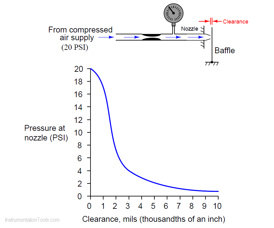
As you can see, this is a very sensitive mechanism. A nearly full swing of pressure (0 PSI to supply) is obtained with just several thousandths of an inch of baffle movement. It is this extreme sensitivity that allows us to assume there is negligible motion in a pneumatic force-balance mechanism operating within its calibrated range.

However, the baffle/nozzle mechanism is certainly not equally sensitive throughout all portions of its operating range.

Identify the most sensitive portion of its range on the transfer function graph, and explain you selection criterion.

Answer:

The most sensitive portion of this mechanism’s range is where the derivative of the transfer function reaches its maximum (absolute) value.

Most sensitive where dP/dx is at its greatest (absolute) value

Where,

P = Pressure at nozzle

x = Clearance between baffle and nozzle

The answer refers to the calculus principle of the derivative.

In plain English, the most sensitive range of the baffle/nozzle mechanism is where the graph is steepest:

Baffle Nozzle Assembly Sensitive Mechanism

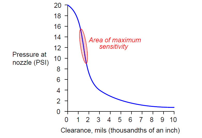
This is where the gain of the system is greatest.

Read Next:

  • Pneumatic Elements
  • Thermowell Insertion
  • Pneumatic Relay
  • Flapper-Nozzle Regulator
  • Vibration Switch Principle

Credits: Tony R. Kuphaldt

Don't Miss Our Updates
Be the first to get exclusive content straight to your email.
We promise not to spam you. You can unsubscribe at any time.
Invalid email address
You've successfully subscribed !

Continue Reading

How much Pressure will Remote Seal Pressure Transmitter Indicate?
Identify Two Pressure Switches Logic
Pneumatic Level Transmitter Calibration Table
Practical Process Control System Questions & Answers – 9
Question on Remote Seal with Capillary Tubing Transmitter
Calculate Amount of Weight Indicated by the Scale
Share This Article
Facebook Whatsapp Whatsapp LinkedIn Copy Link
Share
Leave a Comment

Leave a Reply Cancel reply

Your email address will not be published. Required fields are marked *

Stay Connected

128.3kFollowersLike
69.1kFollowersFollow
210kSubscribersSubscribe
38kFollowersFollow

Categories

Explore More

Programmable Logic Controller (PLC) Questions and Answers – 17
Programmable Logic Controller (PLC) Questions and Answers – 11
Which Tube has most Hydrostatic Pressure?
LRV and URV of PT for Extreme Limits of Empty and Full
Galileo Thermometer
Oil and Air Pressure Actuated Lifts Questions
Programmable Logic Controller (PLC) Questions and Answers – 6
Liquid Level Switch Control Logic

Keep Learning

Allen-Bradley PLC Program

Troubleshoot Allen Bradley PLC Logic

Motor ladder Logic

Draw a ladder logic circuit for the electric motor of an air compressor ?

Calculate LRV and URV for 4-20 mA Loop-powered DP Transmitter

Calculate LRV and URV for 4-20 mA Loop-powered DP Transmitter

Resistance Temperature Detector (RTD) Questions

Resistance Temperature Detector (RTD) Questions – 1

surface-mounted water pump

Surface-mounted Water Pump

Determine the Problems with the Level Transmitter and Gauge

Determine the Problems with Level Transmitter and Gauge

Foxboro pneumatic instruments

Pneumatic Force Balance Instrument

DP Transmitter Block and Bleed Valve

DP Transmitter Block and Bleed Valves

Learn More

PCB Making Machine

Beyond FR-4: Exploring Novel Materials for PCB Fabrication

What is Power Cable

What is Power Cable? Types of Power Cables

What is a Filter Circuit

What is a Filter Circuit ?

What is PCB Corrosion - Electronic Boards Corrosion Prevention

What is PCB Corrosion? Electronic Boards Corrosion Prevention

Fiber Optic Cable - Method of Joining and Fusion Splicing

Fiber Optic Cable – Method of Joining and Fusion Splicing

Electric Circuits Objective Questions

Electric Circuits Objective Questions – Set 14

Automatic Car Door Simulation

Automatic Door Operation PLC Programming and Simulation

Types of Motor Enclosures

Types of Motor Enclosures

Menu

  • About
  • Privacy Policy
  • Copyright

Quick Links

  • Learn PLC
  • Helping Hand
  • Part Time Job

YouTube Subscribe

Follow US
All rights reserved. Reproduction in whole or in part without written permission is prohibited.
Welcome Back!

Sign in to your account

Username or Email Address
Password

Lost your password?